
Page 255 - Rashid, Power Electronics Handbook
P. 255
244 J. Espinoza
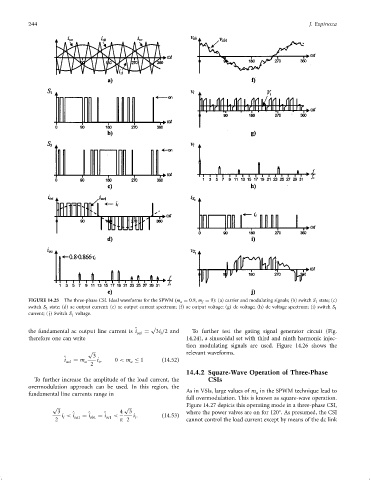
FIGURE 14.25 The three-phase CSI. Ideal waveforms for the SPWM ðm a ¼ 0:8, m f ¼ 9): (a) carrier and modulating signals; (b) switch S 1 state; (c)
switch S 3 state; (d) ac output current; (e) ac output current spectrum; (f) ac output voltage; (g) dc voltage; (h) dc voltage spectrum; (i) switch S 1
current; ( j) Switch S 1 voltage.
p
the fundamental ac output line current is i ^ oa1 ¼ 3i =2 and To further test the gating signal generator circuit (Fig.
i
therefore one can write 14.24), a sinusoidal set with third and ninth harmonic injec-
tion modulating signals are used. Figure 14.26 shows the
p relevant waveforms.
3
^ i ¼ m i ; 0 < m 1 ð14:52Þ
oa1 a i a
2
14.4.2 Square-Wave Operation of Three-Phase
To further increase the amplitude of the load current, the CSIs
overmodulation approach can be used. In this region, the
As in VSIs, large values of m in the SPWM technique lead to
a
fundamental line currents range in
full overmodulation. This is known as square-wave operation.
p p Figure 14.27 depicts this operating mode in a three-phase CSI,
3 4 3 where the power valves are on for 120 . As presumed, the CSI
i < i ^ oa1 ¼ i ^ ob1 ¼ i ^ oc1 < i : ð14:53Þ
i
i
2 p 2 cannot control the load current except by means of the dc link