Page 260 - Rashid, Power Electronics Handbook
P. 260

14  Inverters                                                                                       249


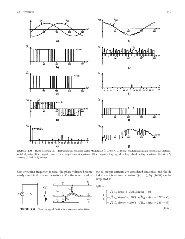
                 FIGURE 14.33  The three-phase CSI. Ideal waveforms for space-vector Modulation ð ^ i c ¼ 0:8, f sn ¼ 18Þ: (a) modulating signals; (b) switch S 1 state; (c)
                 switch S 3 state; (d) ac output current; (e) ac output current spectrum; (f) ac output voltage; (g) dc voltage; (h) dc voltage spectrum; (i) switch S 1
                 current; (j) Switch S 1 voltage.


                 high switching frequency is used, the phase voltages become  the ac output currents are considered sinusoidal and the dc
                 nearly sinusoidal balanced waveforms. On the other hand, if  link current is assumed constant i ðtÞ¼ I , Eq. (14.59) can be
                                                                                                  i     i
                                                                      simpli®ed to

                                                                      v ðtÞ¼
                                                                       i
                                                                               p            p
                                                                            8                                    9
                                                                                 2V sinðotÞ   2I sinðot ÿ fÞ
                                                                            >      on          o1                      >
                                                                            >                                          >
                                                                           1  <  p             p                 =


                                                                             þ 2V sinðot ÿ 120 Þ    2I sinðot ÿ 120 ÿ fÞ
                                                                                   on
                                                                                                     o1
                                                                           I >                                         >
                                                                           i >  p              p                 >
                                                                            :                                          ;
                                                                             þ 2V sinðot ÿ 240 Þ    2I sinðot ÿ 240 ÿ fÞ
                                                                                                     o1
                                                                                   on
                                                                                                                   ð14:60Þ
                   FIGURE 14.34  Phase voltage de®nition in a wye-connected ®lter.
   255   256   257   258   259   260   261   262   263   264   265