Page 262 - Rashid, Power Electronics Handbook
P. 262

14  Inverters                                                                                       251

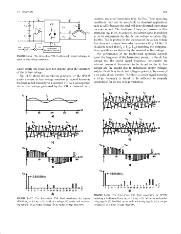
                                                                      contains low-order harmonics (Fig. 14.37e). These operating
                                                                      conditions may not be acceptable in standard applications
                                                                      such as ASDs because the load will draw distorted three-phase
                                                                      currents as well. The feedforward loop performance is illu-
                                                                      strated in Fig. 14.38. As expected, the carrier signal is modi®ed
                                                                      so as to compensate for the dc bus voltage variation (Fig.
                                                                      14.38b). This is probed by the spectrum of the ac line voltage
                                                                      that does not contain low-order harmonics (Fig. 14.38e). It
                                                                      should be noted that ^ v > ^ v , ^ v ; therefore, the compensa-
                                                                                        D
                                                                                                 cb1
                                                                                             ca1
                                                                      tion capabilities are limited by the required ac line voltage.
                                                                        The performance of the feedforward approach depends
                 FIGURE 14.36  The three-phase VSI. Feedforward control technique to
                                                                      upon the frequency of the harmonics present in the dc bus
                 reject dc bus voltage variations.
                                                                      voltage and the carrier signal frequency. Fortunately, the
                                                                      relevant unwanted harmonics to be found in the dc bus
                                                                      voltage are the second due to unbalanced supply voltages,
                 where clearly the result does not depend upon the variations
                                                                      and=or the sixth as the dc bus voltage is generated by means of
                 of the dc bus voltage.
                                                                      a six-pulse diode recti®er. Therefore, a carrier signal featuring
                   Fig. 14.37 shows the waveforms generated by the SPWM
                                                                      a 15-pu frequency is found to be suf®cient to properly
                 under a severe dc bus voltage variation (a second harmonic
                                                                      compensate for dc bus voltage variations.
                 has been added manually to a constant V ). As a consequence,
                                                   i
                 the ac line voltage generated by the VSI is distorted as it


                                                                      FIGURE 14.38  The three-phase VSI. Ideal waveforms for SPWM
                 FIGURE 14.37  The three-phase VSI. Ideal waveforms for regular  including a feedforward loop ðm a ¼ 0:8, m f ¼ 9): (a) carrier and modu-
                 SPWM ðm a ¼ 0:8, m f ¼ 9): (a) dc bus voltage; (b) carrier and modulat-  lating signals; (b) Modi®ed carrier and modulating signals; (c) ac output
                 ing signals; (c) ac output voltage; (d) ac output voltage spectrum.  voltage; (d) ac output voltage spectrum.
   257   258   259   260   261   262   263   264   265   266   267