
Page 257 - Rashid, Power Electronics Handbook
P. 257
246 J. Espinoza
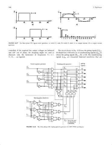
FIGURE 14.27 The three-phase CSI. Square-wave operation: (a) switch S 1 state; (b) switch S 3 state; (c) ac output current; (d) ac output current
spectrum.
controlled. If the required line output voltages are balanced The circuit shown in Fig. 14.28 uses the gating signals S
a 123
and 120 out of phase, the chopping angles are used to developed for a VSI and a set of synchronizing signals i to
c abc
eliminate only the harmonics at frequencies h ¼ 5; 7; obtain the gating signals S 1...6 for a CSI. The synchronizing
11; 13; ... as required. signals i are sinusoidal balanced waveforms that are
c abc
FIGURE 14.28 The three-phase CSI. Gating pattern generator for SHE PWM techniques.