
Page 258 - Rashid, Power Electronics Handbook
P. 258
14 Inverters 247
14.4.4 Space-Vector-based Modulating
Techniques in CSIs
The objective of the space vector (SV)-based modulating
technique is to generate PWM load line currents that are on
average equal to given load line currents. This is done digitally
in each sampling period by properly selecting the switch states
from the valid ones of the CSI (Table 14.4) and the proper
calculation of the period of times they are used. As in VSIs, the
selection and time calculations are based upon the space-
vector transformation.
ˆ
i oa1 i / i 14.4.4.1 Space-Vector Transformation in CSIs
Similarly to VSIs, the vector of three-phase line-modulating
T
signals i ¼i i i can be represented by the complex
FIGURE 14.29 Chopping angles for SHE and fundamental current c abc ca cb cc T
vector I ¼i ¼i i by means of Eqs. (14.35) and
control in three-phase CSIs: ®fth and seventh harmonic elimination. c c ab ca cb
(14.36). For three-phase balanced sinusoidal modulating
^
waveforms, which feature an amplitude i and an angular
c
frequency o, the resulting modulating signals complex vector
^
synchronized with the signals S in order to symmetrically I ¼i becomes a vector of ®xed module i , which rotates
c
c ab
c
a 123
distribute the shorting pulse and thus generate symmetrical at frequency o (Fig. 14.31). Similarly, the SV transformation is
gating patterns. The circuit ensures line current waveforms as applied to the line currents of the nine states of the CSI
the line voltages in a VSI. Therefore, any arbitrary number of normalized with respect to i , which generates nine space
i
harmonics can be eliminated and the fundamental line current vectors (I , i ¼ 1; 2; ... , 9 in Fig. 14.31). As expected, I to
1
i
can be controlled in CSIs. Moreover, the same chopping angles I are nonnull line current vectors and I , I , and I are null
7
6
8
9
obtained for VSIs can be used in CSIs. line current vectors.
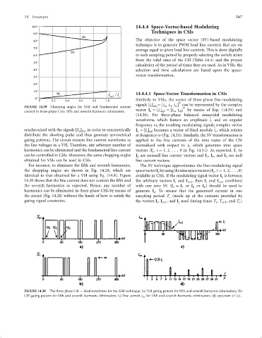
For instance, to eliminate the ®fth and seventh harmonics, The SV technique approximates the line-modulating signal
the chopping angles are shown in Fig. 14.29, which are spacevectorI byusingtheninespacevectors(I ; i ¼ 1; 2; ... ,9)
i
c
identical to that obtained for a VSI using Eq. (14.9). Figure available in CSIs. If the modulating signal vector I is between
c
14.30 shows that the line current does not contain the ®fth and the arbitrary vectors I and I iþ1 , then I and I iþ1 combined
i
i
the seventh harmonics as expected. Hence, any number of with one zero SV (I ¼ I or I or I ) should be used to
z 7 8 9
harmonics can be eliminated in three-phase CSIs by means of generate I . To ensure that the generated current in one
c
the circuit (Fig. 14.28) without the hassle of how to satisfy the sampling period T (made up of the currents provided by
s
gating signal constrains. the vectors I , I , and I used during times T , T , and T )
i iþ1 z i iþ1 z
FIGURE 14.30 The three-phase CSI Ð ideal waveforms for the SHE technique: (a) VSI gating pattern for ®fth and seventh harmonic elimination; (b)
CSI gating pattern for ®fth and seventh harmonic elimination; (c) line current i oa for ®fth and seventh harmonic elimination; (d) spectrum of (c).