
Page 263 - Rashid, Power Electronics Handbook
P. 263
252 J. Espinoza
Unbalanced loads generate a dc input current i that 14.5.3 Feedback Techniques in Voltage Source
i
contains a second harmonic, which contributes to the dc Inverters
bus voltage variation. The previous feedforward approach
Unlike the feedforward approach, the feedback techniques
can compensate for such perturbation and maintain balanced
correct the input to the system (gating signals) depending
ac load voltages.
upon the deviation of the output to the system (e.g., ac load
Digital techniques can also be modi®ed in order to compen-
line currents in VSIs). Another important difference is that
sate for dc bus voltage variations by means of a feedforward
feedback techniques need to sense the controlled variables. In
approach. For instance, the SVM techniques indicate that the general, the controlled variables (output to the system) are
on-times of the vectors V , V iþ1 , and V are chosen according to the control objectives. For instance, in
i
z
ASDs, it is usually necessary to keep the motor line currents
T ¼ T ^ v sinðp=3 ÿ yÞ ð14:65Þ equal to a given set of sinusoidal references. Therefore, the
c
s
i
controlled variables become the ac line currents. There are
T iþ1 ¼ T ^ v sinðyÞ ð14:66Þ several alternatives to implement feedback techniques in VSIs,
s
c
and three of them are discussed in the following.
T ¼ T ÿ T ÿ T iþ1 ð14:67Þ
z
i
s
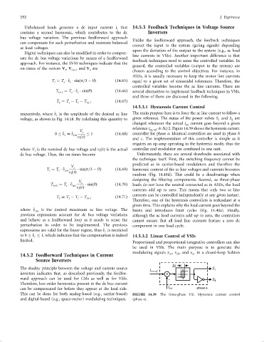
14.5.3.1 Hysteresis Current Control
respectively, where ^ v is the amplitude of the desired ac line The main purpose here is to force the ac line current to follow a
c
voltage, as shown in Fig. 14.18. By rede®ning this quantity to given reference. The status of the power valves S and S are
4
1
changed whenever the actual i oa current goes beyond a given
reference i Di=2. Figure 14.39 shows the hysteresis current
V i oa;ref
0 ^ v ¼ ^ v cm 1 ð14:68Þ controller for phase a. Identical controllers are used in phase b
c
v ðtÞ and c. The implementation of this controller is simple as it
i
requires an op-amp operating in the hysteresis mode, thus the
where V is the nominal dc bus voltage and v ðtÞ is the actual controller and modulator are combined in one unit.
i i
dc bus voltage. Thus, the on-times become Unfortunately, there are several drawbacks associated with
the technique itself. First, the switching frequency cannot be
predicted as in carrier-based modulators and therefore the
V i
T ¼ T ^ v cm sinðp=3 ÿ yÞ ð14:69Þ harmonic content of the ac line voltages and currents becomes
i
s
v ðtÞ
i random (Fig. 14.40d). This could be a disadvantage when
designing the ®ltering components. Second, as three-phase
V i
T iþ1 ¼ T ^ v cm sinðyÞ ð14:70Þ loads do not have the neutral connected as in ASDs, the load
s
v ðtÞ
i
currents add up to zero. This means that only two ac line
currents can be controlled independently at any given instant.
T ¼ T ÿ T ÿ T ð14:71Þ
z s i iþ1
Therefore, one of the hysteresis controllers is redundant at a
given time. This explains why the load current goes beyond the
where ^ v cm is the desired maximum ac line voltage. The limits and introduces limit cycles (Fig. 14.40a). Finally,
previous expressions account for dc bus voltage variations although the ac load currents add up to zero, the controllers
and behave as a feedforward loop as it needs to sense the cannot ensure that all load line currents feature a zero dc
perturbation in order to be implemented. The previous component in one load cycle.
expressions are valid for the linear region, thus ^ v is restricted
c
to 0 ^ v 1, which indicates that the compensation is indeed 14.5.3.2 Linear Control of VSIs
c
limited.
Proportional and proportional-integrative controllers can also
be used in VSIs. The main purpose is to generate the
modulating signals v , v , and v cc in a closed-loop fashion
ca
cb
14.5.2 Feedforward Techniques in Current
Source Inverters
The duality principle between the voltage and current source
inverters indicates that, as described previously, the feedfor-
ward approach can be used for CSIs as well as for VSIs.
Therefore, low-order harmonics present in the dc bus current
can be compensated for before they appear at the load side.
This can be done for both analog-based (e.g., carrier-based) FIGURE 14.39 The three-phase VSI. Hysteresis current control
and digital-based (e.g., space-vector) modulating techniques. (phase a).