
Page 268 - Rashid, Power Electronics Handbook
P. 268
14 Inverters 257
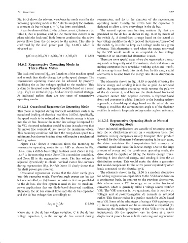
Fig. 14.46 shows the relevant waveforms in steady state for the regeneration, and Dt is the duration of the regeneration
motoring operating mode of the ASD. To simplify the analysis, operating mode. Usually, the drives have the capacitor C
a constant dc bus voltage v ¼ V has been considered. designed to allow a 10% overvoltage in the dc bus.
i
i
It can be observed that: (i) the dc bus current i features a dc The second option uses burning resistors R R that are
i
value I that is positive; and (ii) the motor line current is in paralleled in the dc bus as shown in Fig. 14.48 by means of
i
phase with the back-emf. Both features con®rm that the active the switch S . A closed-loop strategy based on the actual dc
R
power ¯ows from the dc source to the motor. This also is bus voltage modi®es the duty cycle of the turn-on=turn-off of
con®rmed by the shaft power plot (Fig. 14.46f), which is the switch S in order to keep such voltage under to a given
R
obtained as: reference. This alternative is used when the energy recovered
by the VSI would result in an acceptable dc bus voltage
p ðtÞ¼ e ðtÞi ðtÞþ e ðtÞi ðtÞþ e ðtÞi ðtÞ ð14:85Þ variation if an uncontrolled alternative is used.
la
c
l
lb
b
lc
a
There are some special cases where the regeneration operat-
ing mode is frequently used. For instance, electrical shovels in
14.6.2 Regenerative Operating Mode in
Three-Phase VSISs mining companies have repetitive working cycles and 15%
of the energy is sent back into the dc bus. In this case, a valid
The back-emf sources e are functions of the machine speed alternative is to send back the energy into the ac distribution
abc
and as such they ideally change just as the speed changes. The system.
regeneration operating mode can be achieved by properly The schematic shown in Fig. 14.49 is capable of taking the
modifying the ac line voltages applied to the machine. This kinetic energy and sending it into the ac grid. As reviewed
is done by the speed outer loop that could be based on a scalar earlier, the regeneration operating mode reverses the polarity
(e.g., V=f ) or vectorial (e.g., ®eld-oriented) control strategy. of the dc current i , and because the diode-based front-end
i
As indicated earlier, there are two cases of regenerative converter cannot take negative currents, a thyristor-based
operating modes. front-end converter is added. Similarly to the burning-resistor
approach, a closed-loop strategy based on the actual dc bus
14.6.2.1 Occasional Regenerative Operating Mode voltage v modi®es the commutation angle a of the thyristor
i
This mode is required during transient conditions such as in recti®er in order to keep such voltage under a given reference.
occasional braking of electrical machines (ASDs). Speci®cally,
the speed needs to be reduced and the kinetic energy is taken
into the dc bus. Because the motor line voltage is imposed by 14.6.2.2 Regenerative Operating Mode as Normal
the VSI, the speed reduction should be done in such a way that Operating Mode
the motor line currents do not exceed the maximum values. Fewer industrial applications are capable of returning energy
This boundary condition will limit the ramp-down speed to a into the ac distribution system on a continuous basis. For
minimum, but shorter braking times will require a mechanical instance, mining companies usually transport their product
braking system. downhill for few kilometers before processing it. In such cases,
Figure 14.47 shows a transition from the motoring to the drive maintains the transportation belt conveyor at
regenerative operating mode for an ASD as shown in Fig. constant speed and takes the kinetic energy. Due to the large
14.45. Here, a stiff dc bus voltage has been used. Zone I in Fig. amount of energy and the continuous operating mode, the
14.47 is the motoring mode, Zone II is a transition condition, drive should be capable of taking the kinetic energy, trans-
and Zone III is the regeneration mode. The line voltage is forming it into electrical energy, and sending it into the ac
adjusted dynamically to obtain nominal motor line currents distribution system. This would make the drive a generator
during regeneration (Fig. 14.47d). Zone III clearly shows that that would compensate for the active power required by other
the shaft power gets reversed. loads connected to the electrical grid.
Occasional regeneration means that the drive rarely goes The schematic shown in Fig. 14.50 is a modern alternative
into this operating mode. Therefore, such energy can be: (a) for adding regeneration capabilities to the VSI-based drive on
left uncontrolled; or (b) burned in resistors that are paralleled a continuous basis. In contrast to the previous alternatives,
to the dc bus. The ®rst option is used in low- to medium- this scheme uses a VSI topology as an active front-end
power applications that use diode-based front-end recti®ers. converter, which is generally called a voltage-source recti®er
Therefore, the dc bus current ¯ows into the dc bus capacitor VSR. The VSR operates in two quadrants, that is positive dc
and the dc bus voltage rises accordingly to voltages and at positive=negative dc currents as reviewed
earlier. This feature makes it a perfect match for ASDs based
1 on a VSI. Some of the advantages of using a VSR topology are:
Dv ¼ I Dt ð14:86Þ
i
i
C (i) the ac supply current can be as sinusoidal as required (by
increasing the switching frequency of the VSR or the ac line
where Dv is the dc bus voltage variation, C is the dc bus inductance); (ii) the operation can be done at a unity
i
voltage capacitor, I is the average dc bus current during displacement power factor in both motoring and regenerative
i