
Page 273 - Rashid, Power Electronics Handbook
P. 273
262 J. Espinoza
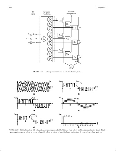
FIGURE 14.54 Multistage converter based on a multicell arrangement.
FIGURE 14.55 Multicell topology. Cell voltages in phase a using a unipolar SPWM (m f ¼ 6, m a ¼ 0:8): (a) Modulating and carrier signals; (b) cell
c 11 ac output voltage; (c) cell c 21 ac output voltage; (d) cell c 31 ac output voltage; (e) phase a load voltage. (f) phase a load-voltage spectrum.