
Page 274 - Rashid, Power Electronics Handbook
P. 274
14 Inverters 263
In general, due to the fact that n ¼ 3 cells are connected in n set of supply voltages that should be 60 =n out of phase is
c
s
s
series in each phase, n carriers are required, which should be required. This would ensure the ®rst set of unwanted current
c
c ¼ 360 =n out of phase. The number of cells per phase n c harmonics at 6 n 1.
c
s
depends on the required phase voltage. For instance, a 600-V The con®guration depicted in Fig. 14.54 contains n ¼ 9
c
p
dc cell generates an ac voltage of 600= 2 ¼ 424 V. Then cells, and a transformer capable of providing n ¼ 9 sets of
s
three cells connected in series generate a phase voltage three-phase voltages that should be 60 =n ¼ 60 =9 out of
s
p
of 3 424 ¼ 1:27 kV, which in turn generates a 1:27 3 ¼ phase to form an N ¼ 6 n ¼ 6 9 ¼ 54-pulse con®guration
s
2:2-kV line-to-line voltage. is required. Although this alternative would provide a near-
Phases b and c are generated similarly to phase a. However, sinusoidal overall supply current, a fewer number of pulses is
the modulating signals v and v should be 120 out of phase. also acceptable that would reduce the transformer complexity.
cb cc
In order to use identical carrier signals in phases b and c, the An N ¼ 18-pulse con®guration usually satis®es all the
carrier-normalized frequency m should be a multiple of 3. requirements. In the example, this con®guration can be
f
Thus, three modulating signals and n carrier signals are achieved by means of a transformer with n ¼ 9 isolated
c c
required to generate three phase voltages by means of a secondaries; however, only n ¼ 3 set of three-phase voltages
s
multicell approach, where n depends upon the required that are 60 =n ¼ 60 =3 ¼ 20 out of phase are generated (Fig.
c s
load line voltage and the dc bus voltage of each cell. 14.54). The con®guration of the transformer restricts the
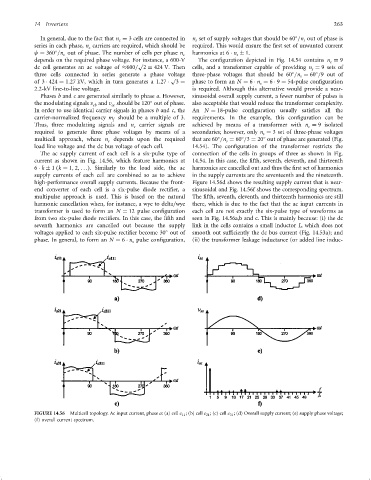
The ac supply current of each cell is a six-pulse type of connection of the cells in groups of three as shown in Fig.
current as shown in Fig. 14.56, which feature harmonics at 14.54. In this case, the ®fth, seventh, eleventh, and thirteenth
6 k 1 ðk ¼ 1; 2; ...Þ. Similarly to the load side, the ac harmonics are cancelled out and thus the ®rst set of harmonics
supply currents of each cell are combined so as to achieve in the supply currents are the seventeenth and the nineteenth.
high-performance overall supply currents. Because the front- Figure 14.56d shows the resulting supply current that is near-
end converter of each cell is a six-pulse diode recti®er, a sinusoidal and Fig. 14.56f shows the corresponding spectrum.
multipulse approach is used. This is based on the natural The ®fth, seventh, eleventh, and thirteenth harmonics are still
harmonic cancellation when, for instance, a wye to delta=wye there, which is due to the fact that the ac input currents in
transformer is used to form an N ¼ 12 pulse con®guration each cell are not exactly the six-pulse type of waveforms as
from two six-pulse diode recti®ers. In this case, the ®fth and seen in Fig. 14.56a,b and c. This is mainly because: (i) the dc
seventh harmonics are cancelled out because the supply link in the cells contains a small inductor L, which does not
voltages applied to each six-pulse recti®er become 30 out of smooth out suf®ciently the dc bus current (Fig. 14.53a); and
phase. In general, to form an N ¼ 6 n pulse con®guration, (ii) the transformer leakage inductance (or added line induc-
s
FIGURE 14.56 Multicell topology. Ac input current, phase a: (a) cell c 11 ; (b) cell c 21 ; (c) cell c 31 ; (d) Overall supply current; (e) supply phase voltage;
(f) overall current spectrum.