Page 272 - Rashid, Power Electronics Handbook
P. 272

14  Inverters                                                                                       261


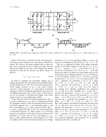
                 FIGURE 14.53  Three-phase-input single-phase output cell: (a) power topology; (b) ac input current, phase a; (c) ac output voltage (m f ¼ 6,
                 m a ¼ 0:8).


                   Figure 14.54 shows a multicell converter that generates a  harmonics  6   m in the load-phase voltage v , that is, the
                                                                                                             an
                                                                                     f
                 three-phase output voltage out of a three-phase ac distribution  lowest set of harmonics in Fig. 14.55f) is 6   m ¼ 6   6 ¼ 36.
                                                                                                            f
                 system. The structure uses three standard cells (as shown in  This can be explained as follows. The voltage harmonics
                 Fig. 14.53) connected in series to form one phase; thus the  present in the PWM voltage of each cell are at l   m   k,
                                                                                                                    f
                 phase-load voltages are the sum of the single-phase voltages  l ¼ 2; 4; ... (where k ¼ 1; 3; 5; ...); for instance, for m ¼ 6,
                                                                                                                   f
                 generated by each cell. For instance, the phase voltage a is  the ®rst set of harmonics is at 12   1; 12   3; ... in all cells.
                 given by                                             Because the cells in one phase use carrier signals that are 120
                                                                      out of phase, all the voltage harmonics  l   m in all cells are
                                                                                                            f

                                 v an  ¼ v o11  þ v o21  þ v o31  ð14:87Þ  l   120 out of phase. Therefore, for l ¼ 2, the cell c 11  generates
                                                                      the harmonics l   m   k ¼ 2   m   k at a given phase j, the
                                                                                      f          f
                   In order to maximize the load-phase voltages, the ac  cell c  generates the harmonics 2   m   k at a phase
                                                                           21                            f


                 voltages generated by the cells should feature identical funda-  j þ l   120 ¼ j þ 2   120 ¼ j þ 240 ¼ j ÿ 120 , and the
                 mental components. On the other hand, each cell generates a  cell c  generates the harmonics 2   m   k at a phase
                                                                           21                            f


                 PWM voltage waveform at the ac side, which contains  j ÿ l   120 ¼ j ÿ 2   120 ¼ j ÿ 240 ¼ j þ 120 ; thus, if
                 unwanted voltage harmonics. If a carrier-based modulating  the voltages have identical amplitudes, the harmonics
                 technique is used, the harmonics generated by each cell are at   2   m add up to zero. Similarly, for l ¼ 4, the cell c 11
                                                                            f
                 well-de®ned frequencies (Fig. 14.53c). Some of these harmo-  generates the harmonics l   m   k ¼ 4   m   k at a given
                                                                                               f
                                                                                                          f
                 nics are not present in the phase-load voltage if the carrier  phase j, the cell c 21  generates the harmonics 4   m   k at a
                                                                                                                f


                 signals of each cell are properly phase shifted.     phase   j þ l   120 ¼ j þ 4   120 ¼ j þ 480 ¼ j þ 120 ,
                   In fact, Fig. 14.55 shows the voltages generated by cells c ,  and the cell c 21  generates the harmonics 4   m   k at a
                                                                  11
                                                                                                               f


                 c , and c , which are v o11 o21 , and v o31 , respectively, and form  phase  j ÿ l   120 ¼ j ÿ 4   120 ¼ j ÿ 480 ¼ j ÿ 120 ;
                                      ,
                  21
                         31
                 the load-phase voltage a. They are generated using the unipo-  thus, if the voltages have identical amplitudes, the harmonics
                 lar SPWM approach, that is, one modulating signal v ca  and   4   m add up to zero. However, for l ¼ 6, the cell c 11
                                                                            f
                 three carrier signals v , v , and v D3  that are used by cells c ,  generates the harmonics l   m   k ¼ 6   m   k at a given
                                   D1
                                      D2
                                                                                                          f
                                                                  11
                                                                                               f
                 c , and c , respectively (Fig. 14.55a). The carrier signals have  phase j, the cell c 21  generates the harmonics 6   m   k at a
                                                                                                                f
                  21
                         31


                 a normalized frequency m , which ensures an m switching  phase j þ l   120 ¼ j þ 6   120 ¼ j þ 720 ¼ j, and the
                                       f
                                                          f
                 frequency in each power valve and the lowest unwanted set of  cell c 21  generates the harmonics 6   m   k at a phase
                                                                                                         f


                 harmonics  2   m ðm evenÞ in the ac cell voltages v o11 , v o21 ,  j ÿ l   120 ¼ j ÿ 6   120 ¼ j ÿ 720 ; thus, if the voltages
                                f
                                   f
                 and v o31 . More importantly, the carrier signals are c ¼ 120    have identical amplitudes, the harmonics  6   m become
                                                                                                                f
                 out of phase, which ensures the lowest unwanted set of voltage  triplicated rather than cancelled out.
   267   268   269   270   271   272   273   274   275   276   277