
Page 271 - Rashid, Power Electronics Handbook
P. 271
260 J. Espinoza
additional equipment is required to include regeneration option usually avoided as symmetrical sharing of the power is
capabilities in CSI-based drives. not natural in these arrangements.
Similarly, an active front-end recti®er could be used to Two solutions are available to generate near-sinusoidal
improve the overall performance of the thyristor-based recti- voltage waveforms while using six-switch topologies. The
®er. A PWM current-source recti®er CSR could replace the ®rst is a topology based on a CSI in combination with a
thyristor-based recti®er with the following added advantages: capacitive ®lter. The second solution is a topology based on a
(i) the ac supply current can be as sinusoidal as required (e.g., VSI including an inductive or inductive=capacitive ®lter at the
by increasing the switching frequency of the CSR); (ii) the load terminals. Although both alternatives generate near-
operation can be done at a unity displacement power factor in sinusoidal voltage waveforms, both continue sharing the
both motoring and regenerative operating modes; and (iii) the load power only among six power valves.
control of the CSR is done in both motoring and regenerative Solutions based on multistage voltage source topologies
operating modes by a single dc bus current loop. have been proposed. They provide medium voltages at the
ac terminals while keeping low dv=dts and a large number of
power valves that symmetrically share the total load power.
The multistage VSIs can be classi®ed in multicell and multi-
14.7 Multistage Inverters level topologies.
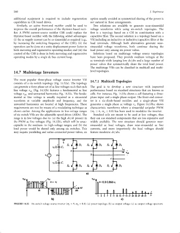
The most popular three-phase voltage source inverter VSI 14.7.1 Multicell Topologies
consists of a six-switch topology (Fig. 14.52a). The topology
can generate a three-phase set of ac line voltages such that each The goal is to develop a new structure with improved
line voltage v ab (Fig. 14.52b) features a fundamental ac line performance based on standard structures that are known as
voltage v ab1 and unwanted harmonics Fig. 14.52c. The funda- cells. For instance, Fig. 14.53a shows a cell featuring a three-
mental ac line voltage is usually required as a sinusoidal phase input and a single-phase output. The front-end conver-
waveform at variable amplitude and frequency, and the ter is a six-diode-based recti®er, and a single-phase VSI
unwanted harmonics are located at high frequencies. These generates a single-phase ac voltage v . Figure 14.53b,c shows
o
requirements are met by means of a modulating technique as characteristic waveforms where a sinusoidal unipolar PWM
shown earlier. Among the applications in low-voltage ranges (m ¼ 6, m ¼ 0:8) has been used to modulate the inverter.
f
a
of six-switch VSIs are the adjustable speed drives (ASDs). The Standard cells are meant to be used at low voltages, thus
range is in low voltages due to: (a) the high dv=dt present in they can use standard components that are less expensive and
the PWM ac line voltages (Fig. 14.52b), which will be unac- widely available. The new structure should generate near-
ceptable in the medium- to high-voltage ranges; and (b) the sinusoidal ac load voltages, draw near-sinusoidal ac line
load power would be shared only among six switches. This currents, and more importantly the load voltages should
may require paralleling and series-connected power valves, an feature moderate dv=dts.
FIGURE 14.52 Six-switch voltage source inverter (m f ¼ 9, m a ¼ 0:8): (a) power topology; (b) ac output voltage; (c) ac output voltage spectrum.