Page 266 - Rashid, Power Electronics Handbook
P. 266

14  Inverters                                                                                       255


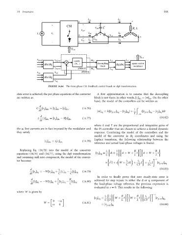
                                       FIGURE 14.44  The three-phase CSI. Feedback control based on dq0 transformation.

                 state error is achieved, the per phase equations of the converter  A ®rst approximation is to assume that the decoupling
                 are written as                                       block is not there; in other words, ‰i Š  ¼‰mŠ . On the other
                                                                                                   c dq    dq
                                                                      hand, the model of the controllers can be written as
                                 d
                               C  ‰v Š  ¼‰i Š  ÿ‰i Š          ð14:76Þ                            1  ð t
                                    p abc
                                                  l abc
                                           o abc
                                dt                                      ‰mŠ  ¼ kf‰v  Š  ÿ‰v Š gþ      ð‰v  Š  ÿ‰v Š Þdt
                                                                           dq     p;ref dq  p dq        p;ref dq  p dq
                                                                                                 T  ÿ1
                                 d
                                L  ‰i Š  ¼‰v Š  ÿ R‰i Š       ð14:77Þ                                              ð14:82Þ
                                                   l abc
                                    l abc
                                           p abc
                                 dt
                                                                      where k and T are the proportional and integrative gains of
                 the ac line currents are in fact imposed by the modulator and  the PI controller that are chosen to achieve a desired dynamic
                 they satisfy                                         response. Combining the model of the controllers and the
                                                                      model of the converter in dq coordinates and using the
                                                                      Laplace transform, the following relationship between the
                                    ‰i Š  ¼ i ‰i Š            ð14:78Þ
                                     o abc
                                            i c abc
                                                                      reference and actual load-phase voltages is found:

                   Replacing Eq. (14.78) into the model of the converter      i i     1          R             R
                 equations (14.76) and (14.77), using the dq0 transformation  ‰v Š  ¼  sk þ  sI þ W þ  I  sI þ W þ  I
                                                                        p dq
                                                                              C      T           L              L
                 and assuming null zero component, the model of the conver-
                                                                                                                ÿ1
                 ter becomes                                                     2          i i     i i    s
                                                                                                                     Š
                                                                               s I þ sW þ    kI þ     I þ    I   ‰v p;ref dq
                                                                                           C       CT     LC
                          d                   i i     1                                                            ð14:83Þ
                            ‰v Š  ¼ÿW‰v Š   þ  ‰i Š  ÿ  ‰i Š  ð14:79Þ
                                                        l dq
                                                c dq
                                        p dq
                              p dq
                          dt                  C       C
                                                                        In order to ®nally prove that zero steady-state error is
                           d                 1       R                achieved for step inputs in either the d or q component of
                             ‰i Š  ¼ÿW‰i Š þ ‰v Š  ÿ   ‰i Š   ð14:80Þ
                                                p dq
                                        l dq
                              l dq
                                                        l dq
                           dt                L       L                the load-phase voltage reference, the previous expression is
                                                                      evaluated in s ¼ 0. This results in the following:
                 where W is given by

                                                                                                               ÿ1
                                                                             i i  1     R          R     i i
                                                                      ‰v Š  ¼       W þ   I   W þ   I      I    ‰v  Š
                                                                       p dq  C T        L          L    CT       p;ref dq
                                          0  ÿo
                                    W ¼                       ð14:81Þ
                                          o   0                            ¼‰v p;ref dq                            ð14:84Þ
                                                                                 Š
   261   262   263   264   265   266   267   268   269   270   271