
Page 265 - Rashid, Power Electronics Handbook
P. 265
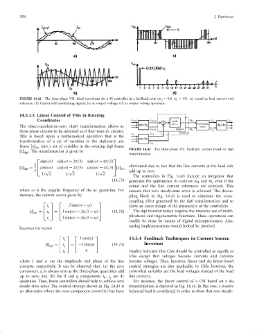
254 J. Espinoza
FIGURE 14.42 The three-phase VSI. Ideal waveforms for a PI controller in a feedback loop ðm a ¼ 0:8, m f ¼ 15): (a) actual ac load current and
reference; (b) Carrier and modulating signals; (c) ac output voltage; (d) ac output voltage spectrum.
14.5.3.3 Linear Control of VSIs in Rotating
Coordinates
The direct-quadrature-zero (dq0) transformation allows ac
three-phase circuits to be operated as if they were dc circuits.
This is based upon a mathematical operation that is the
transformation of a set of variables in the stationary abc
frame x into a set of variables in the rotating dq0 frame
abc FIGURE 14.43 The three-phase VSI. Feedback control based on dq0
x . The transformation is given by
dq0 transformation.
2 3
sinðotÞ sinðot ÿ 2p=3Þ sinðot ÿ 4p=3Þ
2 6 7 eliminated due to fact that the line currents at the load side
x cosðotÞ cosðot ÿ 2p=3Þ cosðot ÿ 4p=3Þ5x
dq0 ¼ 4 abc
3 p p p add up to zero.
1= 2 1= 2 1= 2
The controllers in Fig. 14.43 include an integrator that
ð14:73Þ generates the appropriate dc outputs m and m even if the
q
d
actual and the line current references are identical. This
where o is the angular frequency of the ac quantities. For ensures that zero steady-state error is achieved. The decou-
instance, the current vector given by pling block in Fig. 14.43 is used to eliminate the cross-
coupling effect generated by the dq0 transformation and to
2 3 2 3
i a I sinðot ÿ jÞ allow an easier design of the parameters of the controllers.
6
7
6
7
i abc ¼ 4 i 5 ¼ 4 I sinðot ÿ 2p=3 ÿ jÞ 5 ð14:74Þ The dq0 transformation requires the intensive use of multi-
b
plications and trigonometric functions. These operations can
i I sinðot ÿ 4p=3 ÿ jÞ
c
readily be done by means of digital microprocessors. Also,
analog implementations would indeed be involved.
becomes the vector
2 3 2 3
i d I cosðjÞ 14.5.4 Feedback Techniques in Current Source
6
7
7
6
i dq0 ¼ 4 i 5 ¼ 4 ÿI sinðjÞ 5 ð14:75Þ Inverters
q
i 0 0 Duality indicates that CSIs should be controlled as equally as
VSIs except that voltages become currents and currents
where I and j are the amplitude and phase of the line become voltages. Thus, hystersis, linear and dq linear-based
currents, respectively. It can be observed that: (a) the zero control strategies are also applicable to CSIs; however, the
component i is always zero as the three-phase quantities add controlled variables are the load voltages instead of the load
0
up to zero; and (b) the d and q components i , i are dc line currents.
d
q
quantities. Thus, linear controllers should help to achieve zero For instance, the linear control of a CSI based on a dq
steady-state error. The control strategy shown in Fig. 14.43 is transformation is depicted in Fig. 14.44. In this case, a passive
an alternative where the zero-component controller has been balanced load is considered. In order to show that zero steady-