
Page 270 - Rashid, Power Electronics Handbook
P. 270
14 Inverters 259
FIGURE 14.49 The ASD based on a VSI. Diode-thyristor-based front-end recti®er with regeneration capabilities.
FIGURE 14.50 The ASD based on a VSI. Active front-end recti®er with regeneration capabilities.
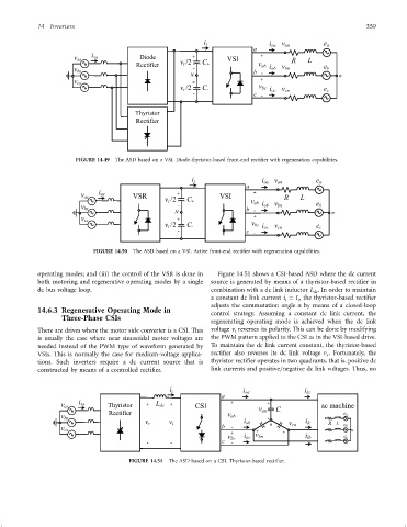
operating modes; and (iii) the control of the VSR is done in Figure 14.51 shows a CSI-based ASD where the dc current
both motoring and regenerative operating modes by a single source is generated by means of a thyristor-based recti®er in
dc bus voltage loop. combination with a dc link inductor L . In order to maintain
dc
a constant dc link current i ¼ I , the thyristor-based recti®er
i
i
adjusts the commutation angle a by means of a closed-loop
14.6.3 Regenerative Operating Mode in control strategy. Assuming a constant dc link current, the
Three-Phase CSIs
regenerating operating mode is achieved when the dc link
There are drives where the motor side converter is a CSI. This voltage v reverses its polarity. This can be done by modifying
i
is usually the case where near sinusoidal motor voltages are the PWM pattern applied to the CSI as in the VSI-based drive.
needed instead of the PWM type of waveform generated by To maintain the dc link current constant, the thyristor-based
VSIs. This is normally the case for medium-voltage applica- recti®er also reverses its dc link voltage v . Fortunately, the
r
tions. Such inverters require a dc current source that is thyristor recti®er operates in two quadrants, that is, positive dc
constructed by means of a controlled recti®er. link currents and positive=negative dc link voltages. Thus, no
FIGURE 14.51 The ASD based on a CSI. Thyristor-based recti®er.