
Page 264 - Rashid, Power Electronics Handbook
P. 264
14 Inverters 253
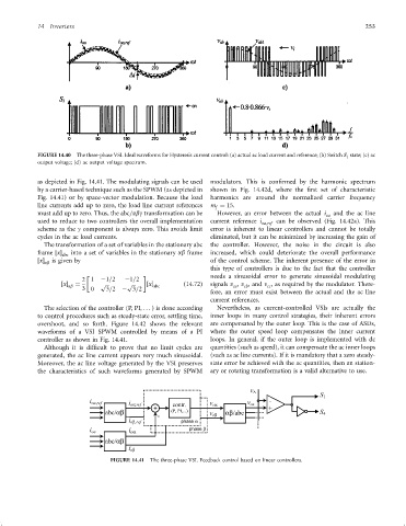
FIGURE 14.40 The three-phase VSI. Ideal waveforms for Hysteresis current control: (a) actual ac load current and reference; (b) Switch S 1 state; (c) ac
output voltage; (d) ac output voltage spectrum.
as depicted in Fig. 14.41. The modulating signals can be used modulators. This is con®rmed by the harmonic spectrum
by a carrier-based technique such as the SPWM (as depicted in shown in Fig. 14.42d, where the ®rst set of characteristic
Fig. 14.41) or by space-vector modulation. Because the load harmonics are around the normalized carrier frequency
line currents add up to zero, the load line current references m ¼ 15.
f
must add up to zero. Thus, the abc=abg transformation can be However, an error between the actual i and the ac line
oa
used to reduce to two controllers the overall implementation current reference i can be observed (Fig. 14.42a). This
oa;ref
scheme as the g component is always zero. This avoids limit error is inherent to linear controllers and cannot be totally
cycles in the ac load currents. eliminated, but it can be minimized by increasing the gain of
The transformation of a set of variables in the stationary abc the controller. However, the noise in the circuit is also
frame x into a set of variables in the stationary ab frame increased, which could deteriorate the overall performance
abc
x ab is given by of the control scheme. The inherent presence of the error in
this type of controllers is due to the fact that the controller
2 1 ÿ1=2 ÿ1=2 needs a sinusoidal error to generate sinusoidal modulating
x ab ¼ p p x abc ð14:72Þ signals v , v , and v , as required by the modulator. There-
cb
ca
cc
3 0 3=2 ÿ 3=2
fore, an error must exist between the actual and the ac line
current references.
The selection of the controller (P, PI, ... ) is done according Nevertheless, as current-controlled VSIs are actually the
to control procedures such as steady-state error, settling time, inner loops in many control strategies, their inherent errors
overshoot, and so forth. Figure 14.42 shows the relevant are compensated by the outer loop. This is the case of ASDs,
waveforms of a VSI SPWM controlled by means of a PI where the outer speed loop compensates the inner current
controller as shown in Fig. 14.41. loops. In general, if the outer loop is implemented with dc
Although it is dif®cult to prove that no limit cycles are quantities (such as speed), it can compensate the ac inner loops
generated, the ac line current appears very much sinusoidal. (such as ac line currents). If it is mandatory that a zero steady-
Moreover, the ac line voltage generated by the VSI preserves state error be achieved with the ac quantities, then an station-
the characteristics of such waveforms generated by SPWM ary or rotating transformation is a valid alternative to use.
FIGURE 14.41 The three-phase VSI. Feedback control based on linear controllers.