
Page 251 - Rashid, Power Electronics Handbook
P. 251
240 J. Espinoza
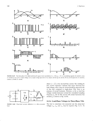
FIGURE 14.19 The three-phase VSI. Ideal waveforms for space-vector modulation (^ v c ¼ 0:8, f sn ¼ 18): (a) modulating signals; (b) switch S 1 state;
(c) switch S 3 state; (d) ac output voltage; (e) ac output voltage spectrum; (f) ac output current; (g) dc current; (h) dc current spectrum; (i) switch S 1
current; (j) diode D 1 current.
p
where I ¼ I is the rms load line current. The resulting dc
l
o
link current expression indicates that under harmonic-free
load voltages, only a clean dc current should be expected in the
dc bus and, compared to single-phase VSIs, there is no
presence of second harmonic. However, as the ac load line
voltages contain harmonics around the normalized sampling
frequency f , the dc link current will contain harmonics but
sn
around f as shown in Fig. 14.19h.
sn
14.3.6 Load-Phase Voltages in Three-Phase VSIs
FIGURE 14.20 Phase-load currents de®nition in a delta-connected The load is sometimes wye-connected and the phase-load
load. voltages v , v ,and v cn may be required (Fig. 14.21). To
bn
an