
Page 247 - Rashid, Power Electronics Handbook
P. 247
236 J. Espinoza
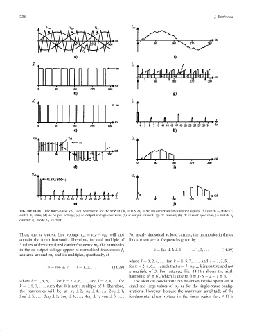
FIGURE 14.14 The three-phase VSI. Ideal waveforms for the SPWM (m a ¼ 0:8, m f ¼ 9): (a) carrier and modulating signals; (b) switch S 1 state; (c)
switch S 3 state; (d) ac output voltage; (e) ac output voltage spectrum; (f) ac output current; (g) dc current; (h) dc current spectrum; (i) switch S 1
current; (j) diode D 1 current.
Thus, the ac output line voltage v ab ¼ v aN ÿ v bN will not For nearly sinusoidal ac load current, the harmonics in the dc
contain the ninth harmonic. Therefore, for odd multiple of link current are at frequencies given by
3 values of the normalized carrier frequency m , the harmonics
f
in the ac output voltage appear at normalized frequencies f h ¼ lm k 1 l ¼ 1; 2; ... ð14:29Þ
h f
centered around m and its multiples, speci®cally, at
f
where l ¼ 0; 2; 4; ... for k ¼ 1; 5; 7; ...,and l ¼ 1; 3; 5; ...
h ¼ lm k l ¼ 1; 2; ... ð14:28Þ for k ¼ 2; 4; 6; ..., such that h ¼ l m k is positive and not
f
f
a multiple of 3. For instance, Fig. 14.14h shows the sixth
harmonic (h ¼ 6), which is due to h ¼ 1 9 ÿ 2 ÿ 1 ¼ 6.
where l ¼ 1; 3; 5; ... for k ¼ 2; 4; 6; ..., and l ¼ 2; 4; ... for The identical conclusions can be drawn for the operation at
k ¼ 1; 5; 7; ... , such that h is not a multiple of 3. Therefore, small and large values of m as for the single-phase con®g-
f
the harmonics will be at m 2, m 4; ... ,2m 1, urations. However, because the maximum amplitude of the
f
f
f
2mf 5; ... ,3m 2, 3m 4; ... ,4m 1, 4m 5; ... . fundamental phase voltage in the linear region (m 1) is
f f f f a