Page 249 - Rashid, Power Electronics Handbook
P. 249

238                                                                                           J. Espinoza


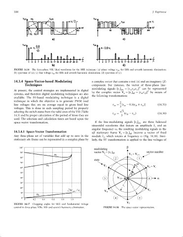
               FIGURE 14.16  The three-phase VSI. Ideal waveforms for the SHE technique: (a) phase voltage v aN for ®fth and seventh harmonic elimination;
               (b) spectrum of (a); (c) line voltage v ab for ®fth and seventh harmonic elimination; (d) spectrum of (c).

               14.3.4 Space-Vector-based Modulating                 a complex vector that contains a real (a) and an imaginary (b)
                       Techniques                                   component. For instance, the vector of three-phase line-
                                                                                                    T
                                                                    modulating signals ‰v Š  ¼‰v v v Š  can be represented
                                                                                      c abc
                                                                                              ca cb cc
               At present, the control strategies are implemented in digital                             T
                                                                    by the complex vector V ¼‰v Š  ¼‰v v Š  by means of
               systems, and therefore digital modulating techniques are also              c   c ab   ca cb
                                                                    the following transformation:
               available. The SV-based modulating technique is a digital
               technique in which the objective is to generate PWM load
                                                                                       2
               line voltages that are on average equal to given load line         v ¼ ‰v ÿ 0:5ðv þ v ފ          ð14:35Þ
                                                                                   ca
                                                                                                      cc
                                                                                                 cb
                                                                                          ca
               voltages. This is done in each sampling period by properly              3 p 
               selecting the switch states from the valid ones of the VSI (Table         3
                                                                                  v cb  ¼  ðv ÿ v Þ              ð14:36Þ
                                                                                           cb
                                                                                                cc
               14.3) and by proper calculation of the period of times they are          3
               used. The selection and calculation times are based upon the
               space-vector transformation.                           If the line-modulating signals ‰v Š  are three balanced
                                                                                                  c abc
                                                                    sinusoidal waveforms that feature an amplitude ^ v and an
                                                                                                               c
                                                                    angular frequency o, the resulting modulating signals in the
               14.3.4.1 Space-Vector Transformation                 ab stationary frame V ¼‰v Š  become a vector of ®xed
                                                                                        c   c ab
               Any three-phase set of variables that add up to zero in the  module ^ v , which rotates at frequency o (Fig. 14.18). Simi-
                                                                            c
               stationary abc frame can be represented in a complex plane by  larly, the SV transformation is applied to the line voltages of


                                                                                         v ˆ
                                                                                          c
                                                      v ˆ 3  aN1  v /  i


               FIGURE 14.17  Chopping angles for SHE and fundamental voltage
               control in three-phase VSIs: ®fth and seventh harmonic elimination.  FIGURE 14.18  The space-vector representation.
   244   245   246   247   248   249   250   251   252   253   254