
Page 111 - Reciprocating Compressors Operation Maintenance
P. 111
98 Reciprocating Compressors: Operation and Maintenance
There are five steps to accomplish the first objective:
1. The safe dynamic soil-bearing capacity must not be exceeded at any
point on the foundation base.
2. The unit loading of the soil must be distributed over the entire area,
3. Foundation block proportions must be such that the resultant verti-
cal load due to the mass of the machine and any unbalanced inertia
force falls within the base area.
4. The foundation must have sufficient mass and bearing area to pre-
vent its sliding on the soil because of any unbalanced forces.
5. Temperature variation in the foundation itself must be uniform to
prevent warping.
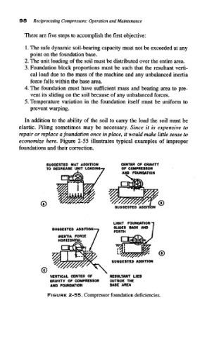
In addition to the ability of the soil to carry the load the soil must be
elastic. Piling sometimes may be necessary. Since it is expensive to
repair or replace a foundation once in place, it would make little sense to
economize here. Figure 2-55 illustrates typical examples of improper
foundations and their correction.
SUGGESTED MAT ADDITION CENTER OF GRAVITY
TO DECREASE UNIT LOADING-? OP COMPRESSOR
FOUNDATION
SUGGESTED ADDITION
LIGHT FOUNDATION "I
SUGGESTED ADDITION-; %££ MC * AN °
i FORTH
INERTIA FORCE
HORIZONTAL
VERTICAL CENTER OF RESULTANT LIES
GRAVITY OF COMPRESSOR OUTSIDE THE
AND FOUNDATION BASE AREA
FIGURE 2-55. Compressor foundation deficiencies.