
Page 116 - Reciprocating Compressors Operation Maintenance
P. 116
Design and Materials for Reciprocating Compressor Components 103
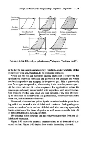
Discharge
pressure
Suction
pressure
Conventional card Normal load, reduced capacity Overload, increased capacity
L Stroke J U Stroke >! N Stroke.
Suction
pressure
Reduced load, reduced capacity Overload, normal capacity
|« Stroke J 1< Stroke J
I I I 1
FIGURE 2-58. Effect of gas pulsations on pV diagrams ("indicator cards").
is the key to the exceptional durability, reliability, and availability of this
compressor type and, therefore, to its economic operation.
Above all, the unique labyrinth sealing technique is employed for
applications where no lubricants are allowed in the cylinder and where
no abrasion particles are accepted in the process gas. This is particularly
true for oxygen compression, where safety is the most important aspect.
At the other extreme, it is also employed for applications where the
process gas is heavily contaminated with impurities, such as polymeriza-
tion products or other very small and hard particles. They have effective-
ly no influence on the labyrinth seal performance, compressor reliability,
wear rate, and maintenance intervals.
Piston and piston rod are guided by the crosshead and the guide bear-
ing which are located in the oil-lubricated crankcase. Both guiding ele-
ments are made of metal and are oil-lubricated, thus assuring a precisely
linear operation of the labyrinth piston as well as an extremely long life
of the piston/piston rod guiding system.
The distance piece separates the gas compressing section from the oil-
lubricated crankcase.
Figure 2-59 shows the essential separation into an oil-free and oil-con-
tacted section. Figure 2-60 depicts flow within the sealing labyrinth.