
Page 254 - Reciprocating Compressors Operation Maintenance
P. 254
Overhaul and Repair of Reciprocating Compressors 239
zontal plane. However, when the 180° position has excessive deflection
(caused by one journal being low), it carries up to the 90° and 270° posi-
tions, which in this case results in the -.001 reading. Furthermore, if the
bearing saddles were out of alignment in a horizontal plane, the signs at
the 90° and 270° positions would be reversed. Therefore, nothing is
wrong with the horizontal alignment. (Actually, the 180° position read-
ings are the most significant, because rarely will main bearing saddles be
found in sidewise misalignment.)
Returning to the example, because the No. 3 throw 180° reading is the
only one that is excessive, it is apparent that the bearing to the right of No. 3
throw is wiped. Note that this low bearing has caused distortion in the shaft
past No. 3 as indicated by the -.002 reading of No. 4 throw. In this case the
correction is simple, because it is only a matter of replacing the bearing.
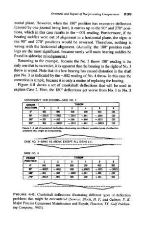
Figure 4-8 shows a set of crankshaft deflections that will be used to
explain Case 2. Here, the 180° deflections get worse from No. 1 to No. 3
CRANKSHAFT DEFLECTIONS-CASE NO. 2
CRANK THROW
POSITION 1 2 3 4 5 €
r 000 000 000 000 000 000
w -.00025 -.0005 -.0015 -.001 -.0005 000
180* -.001 -.003 -.006 -.004 -.0015 000
270° 000 -.00025 -.0015 -.001 -.00025 000
Figure 2~A set of crankshaft deflections illustrating six different possible types of deflection
problems that might be encountered.
CASE NO. 3-SAME AS ABOVE EXCEPT ALL SIGNS (+)
CASE NO. 4
CRANK THROW
POSITION 1 2 3 4 5 6
0° 000 000 000 000 000 000
w —.00025 -.0015 000 +.00025 +.0015 +.00025
180° -.001 -.004 -.0005 +.001 +.005 +.001
270° -.00025 -.001 000 000 +.001 000
FIGURE 4-8. Crankshaft deflections illustrating different types of deflection
problems that might be encountered (Source: Block, H. P. and Geitner, F. K,
Major Process Equipment Maintenance and Repair, Houston, TX, Gulf Publish-
ing Company, 1985).