
Page 385 - Reciprocating Compressors Operation Maintenance
P. 385
37O Reciprocating Compressors: Operation and Maintenance
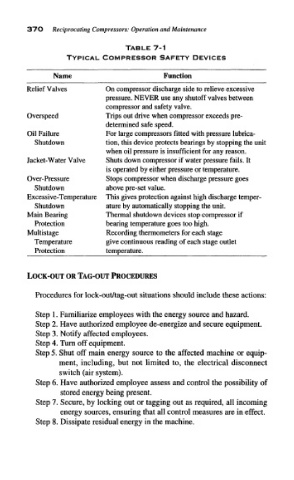
TABLE 7-1
TYPICAL COMPRESSOR SAFETY DEVICES
Name Function
Relief Valves On compressor discharge side to relieve excessive
pressure. NEVER use any shutoff valves between
compressor and safety valve.
Overspeed Trips out drive when compressor exceeds pre-
determined safe speed.
Oil Failure For large compressors fitted with pressure lubrica-
Shutdown tion, this device protects bearings by stopping the unit
when oil pressure is insufficient for any reason.
Jacket- Water Valve Shuts down compressor if water pressure fails. It
is operated by either pressure or temperature.
Over-Pressure Stops compressor when discharge pressure goes
Shutdown above pre-set value.
Excessive-Temperature This gives protection against high discharge temper-
Shutdown ature by automatically stopping the unit.
Main Bearing Thermal shutdown devices stop compressor if
Protection bearing temperature goes too high.
Multistage Recording thermometers for each stage
Temperature give continuous reading of each stage outlet
Protection temperature.
LOCK-OUT OR TAG-OUT PROCEDURES
Procedures for lock-out/tag-out situations should include these actions:
Step 1. Familiarize employees with the energy source and hazard.
Step 2. Have authorized employee de-energize and secure equipment.
Step 3. Notify affected employees.
Step 4. Turn off equipment.
Step 5. Shut off main energy source to the affected machine or equip-
ment, including, but not limited to, the electrical disconnect
switch (air system).
Step 6. Have authorized employee assess and control the possibility of
stored energy being present.
Step 7. Secure, by locking out or tagging out as required, all incoming
energy sources, ensuring that all control measures are in effect.
Step 8. Dissipate residual energy in the machine.