
Page 382 - Reciprocating Compressors Operation Maintenance
P. 382
Preventive Maintenance for Reciprocating Compressors 367
scope. Fortunately, no damage had occurred. The nut was retorqued, along
with other mechanical checks, and the compressor was put back in service.
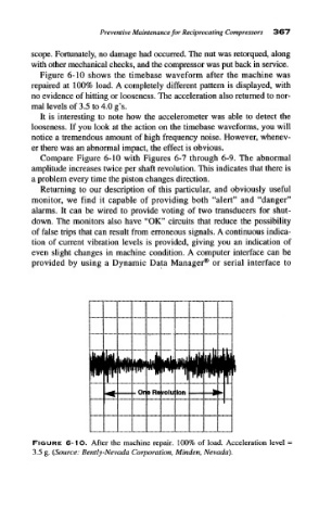
Figure 6-10 shows the timebase waveform after the machine was
repaired at 100% load. A completely different pattern is displayed, with
no evidence of hitting or looseness. The acceleration also returned to nor-
mal levels of 3.5 to 4.0 g's.
It is interesting to note how the accelerorneter was able to detect the
looseness. If you look at the action on the timebase waveforms, you will
notice a tremendous amount of high frequency noise. However, whenev-
er there was an abnormal impact, the effect is obvious.
Compare Figure 6-10 with Figures 6-7 through 6-9. The abnormal
amplitude increases twice per shaft revolution. This indicates that there is
a problem every time the piston changes direction.
Returning to our description of this particular, and obviously useful
monitor, we find it capable of providing both "alert" and "danger"
alarms. It can be wired to provide voting of two transducers for shut-
down. The monitors also have "OK" circuits that reduce the possibility
of false trips that can result from erroneous signals. A continuous indica-
tion of current vibration levels is provided, giving you an indication of
even slight changes in machine condition. A computer interface can be
provided by using a Dynamic Data Manager® or serial interface to
FIGURE 6-1O. After the machine repair. 100% of load. Acceleration level
3.5 g. (Source: Bently-Nevada Corporation, Minden, Nevada).