
Page 158 - Reliability and Maintainability of In service Pipelines
P. 158
Case Studies on the Application of Structural Reliability 143
toughness of the pipe. Based on these two failure modes, two limit state functions
can be established as follows.
5.3.1.2 Strength Limit State
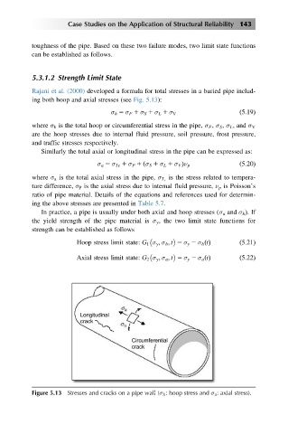
Rajani et al. (2000) developed a formula for total stresses in a buried pipe includ-
ing both hoop and axial stresses (see Fig. 5.13):
σ h 5 σ F 1 σ S 1 σ L 1 σ V ð5:19Þ
where σ h is the total hoop or circumferential stress in the pipe, σ F , σ S , σ L , and σ V
are the hoop stresses due to internal fluid pressure, soil pressure, frost pressure,
and traffic stresses respectively.
Similarly the total axial or longitudinal stress in the pipe can be expressed as:
ð
σ a 5 σ Te 1 σ P 1 σ S 1 σ L 1 σ V Þν p ð5:20Þ
is the stress related to tempera-
where σ a is the total axial stress in the pipe, σ T e
ture difference, σ P is the axial stress due to internal fluid pressure, ν p is Poisson’s
ratio of pipe material. Details of the equations and references used for determin-
ing the above stresses are presented in Table 5.7.
In practice, a pipe is usually under both axial and hoop stresses (σ a and σ h Þ.If
the yield strength of the pipe material is σ y , the two limit state functions for
strength can be established as follows
Hoop stress limit state: G 1 σ y ; σ h ; t 5 σ y 2 σ h tðÞ ð5:21Þ
Axial stress limit state: G 2 σ y ; σ a ; t 5 σ y 2 σ a tðÞ ð5:22Þ
Figure 5.13 Stresses and cracks on a pipe wall (σ h : hoop stress and σ a : axial stress).