
Page 159 - Reliability and Maintainability of In service Pipelines
P. 159
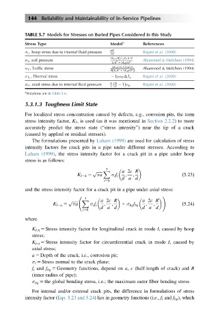
144 Reliability and Maintainability of In-Service Pipelines


           TABLE 5.7 Models for Stresses on Buried Pipes Considered in this Study
           Stress Type                       Model a      References
           σ F , hoop stress due to internal fluid pressure  pD  Rajani et al. (2000)
                                             2d
                                                2
                                             3K m γB C d E P dD
           σ S , soil pressure                  d         Ahammed & Melchers (1994)
                                               3
                                             E P d 1 3K d pD 3
           σ V , Traffic stress              3K m I c C t FE P dD  Ahammed & Melchers (1994)
                                             AE P d 3 1 3K d pD 3  Þ
                                             ð
             , Thermal stress                             Rajani et al. (2000)
           σ T e                             2 E P α P ΔT e

           σ P , axial stress due to internal fluid pressure  p D     Rajani et al. (2000)
                                             2 d  2 1 ν p
           a
           Notations are in Table 5.6.
           5.3.1.3 Toughness Limit State
           For localized stress concentration caused by defects, e.g., corrosion pits, the term
           stress intensity factor, K I , is used (as it was mentioned in Section 2.2.2) to more
           accurately predict the stress state (“stress intensity”) near the tip of a crack
           (caused by applied or residual stresses).
              The formulations presented by Laham (1999) are used for calculation of stress
           intensity factors for crack pits in a pipe under different stresses. According to
           Laham (1999), the stress intensity factor for a crack pit in a pipe under hoop
           stress is as follows:
                                           3
                                      p ffiffiffiffiffiffi X  a 2c R
                                K I2h 5  πa  σ i f i  ;  ;               ð5:23Þ
                                                 d a d
                                          i50
           and the stress intensity factor for a crack pit in a pipe under axial stress:
                                                                 !
                                   3
                            p ffiffiffiffiffiffi X   a 2c R          a 2c R
                      K I2a 5  πa    σ i f i  ;  ;  1 σ bg f bg  ;  ;    ð5:24Þ
                                         d a d           d a d
                                  i50
           where
              K I-h 5 Stress intensity factor for longitudinal crack in mode I, caused by hoop
              stress;
              K I-a 5 Stress intensity factor for circumferential crack in mode I, caused by
              axial stress;
              a 5 Depth of the crack, i.e., corrosion pit;
              σ i 5 Stress normal to the crack plane;
              f i and f bg 5 Geometry functions, depend on a, c (half-length of crack) and R
              (inner radius of pipe);
              σ bg 5 the global bending stress, i.e.; the maximum outer fiber bending stress
              For internal and/or external crack pits, the difference in formulations of stress
           intensity factor (Eqs. 5.23 and 5.24) lies in geometry functions (i.e., f i and f bg ), which