
Page 105 - Renewable Energy Devices and System with Simulations in MATLAB and ANSYS
P. 105
92 Renewable Energy Devices and Systems with Simulations in MATLAB and ANSYS ®
®
temperature conditions. Thereby, the overall efficiency of the PV energy production system is
increased. Numerous techniques have been presented during the last decades for implementing the
MPPT process in a PV system. This chapter provides an overview of the operating principles of
these techniques, which are suited for either uniform or nonuniform solar irradiation conditions.
The operational characteristics and implementation requirements of these MPPT methods are also
analyzed in order to demonstrate their performance features.
5.1 INTRODUCTION
Motivated by the concerns on environmental protection (sustainability) and energy availability, the
installation of photovoltaic (PV) energy production systems has been increased substantially during
the last years. The falling prices of PV modules and more efficient power conversion have assisted in
that direction by enhancing the economic viability of the installed PV systems. More than 40 GW of
new PV capacity was installed across the world during 2014, thus achieving a worldwide cumulative
installed capacity of 178 GW during that year [1].
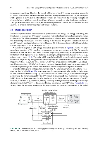
A basic block diagram of a PV energy production system is shown in Figure 5.1, with a PV array
comprising a number of PV modules, a power converter, and also a control unit. The PV source is
connected to a DC/DC or DC/AC power converter, respectively, interfacing the PV-generated power
to the load, which typically is connected to the electric grid, or operates in a stand-alone mode (e.g.,
using a battery bank) [2, 3]. The pulse width modulation (PWM) controller of the control unit is
responsible for producing the appropriate control signals (with an adjustable duty cycle), which drive
the power switches (e.g., metal-oxide-semiconductor field-effect transistors (MOSFETs), insulated-
gate bipolar transistors (IGBTs)) of the power converter. Its operation is based on measurements of
the input/output voltage and current and of internal reference signals of the power converter.
Examples of the power–voltage characteristics of a PV array under various atmospheric condi-
tions are illustrated in Figure 5.2a for the case that the same amount of solar irradiation is incident
on all PV modules of the PV array [2]. It is observed that the power–voltage curves exhibit a unique
point where the power produced by the PV module is maximized (i.e., maximum power point,
MPP). However, in the case that the solar irradiation, which is incident on one or more of the PV
modules, is different (e.g., due to dust, shading caused by buildings or trees), then the power–voltage
characteristic of the PV array is distorted, exhibiting one or more local MPPs (see Figure 5.2b) [4].
Among them, the operating point where the output power is maximized corresponds to the global
DC/DC and/or DC/AC
power converter
+
Power Output Battery
section filter bank
PV PV Output
array current, I pv current, I o Electric
grid
PV Reference Control signal(s): Output
voltage, V pv signals adjustable duty voltage, V o
cycle (D)
PWM
controller
V ref
MPPT
Control unit
FIGURE 5.1 A block diagram of a PV energy production system including a maximum power point tracking
(MPPT) unit to harvest maximum power.