
Page 128 - Renewable Energy Devices and System with Simulations in MATLAB and ANSYS
P. 128
Overview of PV Maximum Power Point Tracking Techniques 115
PV module
DC/DC
converter
with MPPT
controller
DC/DC
converter
with MPPT
controller Load or DC/AC Electric
inverter grid
DC/DC
converter
with MPPT
controller
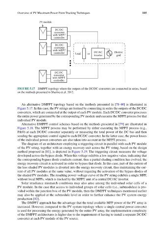
FIGURE 5.17 DMPPT topology where the outputs of the DC/DC converters are connected in series, based
on the methods presented in Sharma et al. 2012.
An alternative DMPPT topology based on the methods presented in [78–80] is illustrated in
Figure 5.17. In this case, the PV strings are formed by connecting in series the outputs of the DC/DC
converters, which are connected at the output of each PV module. Each DC/DC converter processes
the entire power generated by the corresponding PV module and executes the MPPT process for that
individual PV module.
Alternative DMPPT control schemes based on the methods presented in [79] are illustrated in
Figure 5.18. The MPPT process may be performed by either executing the MPPT process (e.g.,
P&O) at each DC/DC converter separately or measuring the total power of the DC bus and then
sending the appropriate control signal to each DC/DC converter. In the latter case, the power losses
of the individual power converters are also taken into account in the MPPT process.
The diagram of an architecture employing a triggering circuit in parallel with each PV module
of the PV string, together with an energy recovery unit across the PV string, based on the design
method proposed in [81], is depicted in Figure 5.19. The triggering circuit measures the voltage
developed across the bypass diode. When this voltage exhibits a low negative value, indicating that
the corresponding bypass diode conducts current, thus a partial shading condition has evolved, the
energy recovery circuit is activated in order to bypass that diode. In this case, part of the current of
the less shaded PV modules is diverted into the energy recovery circuit, thus maintaining the cur-
rent of all PV modules at the same value, without requiring the activation of the bypass diodes of
the shaded PV modules. The resulting power–voltage curve of the PV string exhibits a single MPP,
without local MPPs, which is tracked by the MPPT unit of a central DC/AC inverter.
Solar irradiance mismatch conditions may also arise among the individual solar cells of a
PV module. In the case that access to individual groups of solar cells (i.e., submodules) is pro-
vided within the junction box of the PV module, then the DMPPT techniques mentioned earlier
may also be applied at the submodule level in order to further enhance the PV system energy
production [82].
The DMPPT approach has the advantage that the total available MPP power of the PV array is
increased. However, compared to the PV system topology where a single central power converter
is used for processing the energy generated by the entire PV array, the implementation complexity
of the DMPPT architectures is higher due to the requirement of having to install a separate DC/DC
converter at each PV module of the PV source.