
Page 129 - Renewable Energy Devices and System with Simulations in MATLAB and ANSYS
P. 129
116 Renewable Energy Devices and Systems with Simulations in MATLAB and ANSYS ®
®
PV module #1
MPPT
output voltage algorithm Controller #1 Drive signal #1
and current
PV module #2
MPPT
output voltage algorithm Controller #2 Drive signal #2
and current
PV module #n
MPPT
output voltage algorithm Controller #n Drive signal #n
and current
(a)
Controller #1 Drive signal #1
DC bus
voltage MPPT Controller #2 Drive signal #2
and current algorithm
Controller #n Drive signal #n
(b)
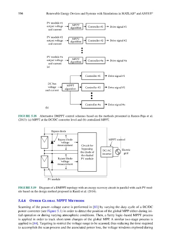
FIGURE 5.18 Alternative DMPPT control schemes based on the methods presented in Ramos-Paja et al.
(2013): (a) MPPT at the DC/DC converter level and (b) centralized MPPT.
Bypass diode
Bypass diode MPPT control
voltage
measurement Circuit for
bypassing Electric
the diode of DC/AC grid
inverter
the shaded
Bypass diode PV module
voltage
measurement
PV module
FIGURE 5.19 Diagram of a DMPPT topology with an energy recovery circuit in parallel with each PV mod-
ule based on the design method proposed in Ramli et al. (2014).
5.4.6 Other Global MPPT Methods
Scanning of the power–voltage curve is performed in [83] by varying the duty cycle of a DC/DC
power converter (see Figure 5.1) in order to detect the position of the global MPP either during ini-
tial operation or during varying atmospheric conditions. Then, a fuzzy logic–based MPPT process
is applied in order to track short-term changes of the global MPP. A similar two-stage process is
applied in [84]. Targeting to restrict the voltage range to be scanned, thus reducing the time required
to accomplish the scan process and the associated power loss, the voltage windows explored during