
Page 124 - Renewable Energy Devices and System with Simulations in MATLAB and ANSYS
P. 124
Overview of PV Maximum Power Point Tracking Techniques 111
Initialization of the algorithm
operational parameters
Produce a new set
of values of the Control the power converter
decision variable to operate at the new
(e.g., duty cycle or operating points V , V , … V k
2
1
reference voltage)
PV module/array output
power measurement at
V , V , … V k
2
1
No
Power comparison among the
alternative operating points
(i.e., P , P , … P )
1
k
2
Termination
criterion satisfied?
Yes
Control the power converter such
that the PV source operates at the
optimal point detected
(a)
Global MPP
output power, P pv P P k 2 1
PV array P 3
P
V 1 V 2 V 3 V k
(b) PV array output voltage, V pv
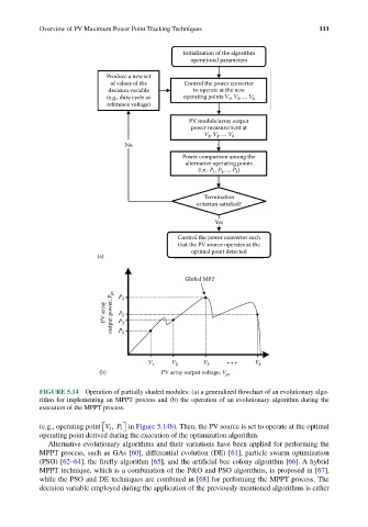
FIGURE 5.14 Operation of partially shaded modules: (a) a generalized flowchart of an evolutionary algo-
rithm for implementing an MPPT process and (b) the operation of an evolutionary algorithm during the
execution of the MPPT process.
(e.g., operating point VP 3 in Figure 5.14b). Then, the PV source is set to operate at the optimal
3 ,
operating point derived during the execution of the optimization algorithm.
Alternative evolutionary algorithms and their variations have been applied for performing the
MPPT process, such as GAs [60], differential evolution (DE) [61], particle swarm optimization
(PSO) [62–64], the firefly algorithm [65], and the artificial bee colony algorithm [66]. A hybrid
MPPT technique, which is a combination of the P&O and PSO algorithms, is proposed in [67],
while the PSO and DE techniques are combined in [68] for performing the MPPT process. The
decision variable employed during the application of the previously mentioned algorithms is either