
Page 120 - Renewable Energy Devices and System with Simulations in MATLAB and ANSYS
P. 120
Overview of PV Maximum Power Point Tracking Techniques 107
The ESC-based MPPT process has the disadvantage that for its implementation in a PV power
processing system, the development of a relatively complex control circuit is required.
5.3.10 MPPT Based on Sliding-Mode Control
In a sliding-mode control for MPPT, the output voltage of the PV source and the current of the
power converter inductor comprise a set of state variables. A switching surface is defined using these
state variables as follows [58]:
(
⋅
c v pv +
Sv pv , ) = c i in − 2 ⋅ V ref (5.17)
i in
1
where
i in is the current of the power converter inductor
c 1 and c 2 are positive constants
V ref is an adjustable control signal
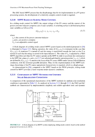
A block diagram of a sliding-mode control MPPT system based on the method proposed in [58]
(
is illustrated in Figure 5.13. During operation, the value of Sv i in , ) is evaluated; in the case that
pv
(
Sv i in , ) > 0, transistor T 1 is turned off and the energy is transferred towards the load, or else T 1 is
pv
turned on such that the energy is stored in the input inductor L. The value of V ref is adjusted by a P&O
MPPT algorithm such that the PV source operates at the MPP. In order to accelerate the convergence
to the MPP, the values of c 1 and c 2 in (5.17) are selected such that the operating points v pv , i in , which
(
are defined by Sv i in , ) = 0, match to the locus of the PV source MPPs under various solar irradiation
pv
conditions, with the minimum possible deviation. Thus, for the implementation of this MPPT tech-
nique, knowledge of the PV source operational characteristics is required, which is a disadvantage.
As demonstrated in [58], compared to the MPPT based on the PWM principle, sliding-mode
control for MPPT provides a faster response under dynamic conditions.
5.3.11 Comparison of MPPT Methods for Uniform
Solar Irradiation Conditions
A comparison of the operational characteristics of the MPPT methods for uniform solar irradiation
conditions is presented in Table 5.2. As analyzed in Sections 5.3.2 through 5.3.3, the P&O and InC
methods are characterized by implementation simplicity and exhibit equivalent static and dynamic
PV array
i in T 1 Driver Load
v pv
c i – c v
2 pv
1 in
+
–
Amplifier
MPPT Comparator
algorithm
V ref with hysteresis
Control unit
FIGURE 5.13 A block diagram of an MPPT system employing sliding-mode control, based on the method
proposed in Levron et al. (2013).