
Page 160 - Renewable Energy Devices and System with Simulations in MATLAB and ANSYS
P. 160
Design of Residential Photovoltaic Systems 147
A more detailed design software allows the user to build and parametrize custom modules, adjust
the PV inverter parameters, calculate and adjust the different losses in the system, and also conduct
yield studies, taking into account the module losses placed in shaded positions.
6.3.2 Comments to the Design Differences for
TF and Crystalline-Si Systems
A residential PV system consists of several elements that can be categorized into four main topics:
1. PV modules—the PV modules on the roof that generate electricity
2. Inverter—the unit that converts the DC power from the modules to AC power usable in the
house
3. Balance of system (BOS) components—cable, mounting structure, fuses, etc.
4. Labor cost—the cost for installing the system (electrician/carpenter)
TF system design is basically similar to cSi system design methodology; however, due to the
lower efficiency and higher output voltage on TF modules, there are some design issues that occur
more often when designing smaller systems using this new PV cell technology.
Furthermore, with TF modules, a PV system requires a larger area for the same kWp installation.
This also means that there are more BOS components and the labor cost is also higher.
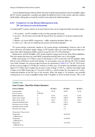
If the same rating of 2.7 kWp is used for the design of a PV system but with TF modules, there
will be some differences in the final design. As an example, one can take the SF 150-S module
from Solar Frontier. Its technical specifications are presented in Table 6.10. The SF 150-S mod-
ule has a power output of 150 Wp per module so in this case, 18 modules are needed to reach the
target of 2.7 kWp. Each module has an open-circuit voltage of 108 V , and the maximum input
DC
voltage of the SMA Sunny Boy 2.5 inverter is 600 V , which results in a maximum of 5 series-
DC
connected modules to the DC bus of the inverter. Since the target is 18 modules, one possible
configuration is to create 6 parallel strings with 3 modules in series for this inverter. This is not
TABLE 6.10
Solar Frontier, Thin-Film Module Datasheet
S-Power Modules SF 145-S SF 150-S SF 155-S
Nominal power P max 145 W 150 W 155 W
Power tolerance +5 W/0 W
Module efficiency % 11.8% 12.2% 12.6%
Open-circuit voltage V oc 107.0 V 108.0 V 109.0 V
Short-circuit current I sc 2.20 A 2.20 A 2.20 A
Current at nominal power I mpp 1.80 A 1.85 A 1.88 A
Maximum system voltage V DC 1000 V
Maximum reverse current 7 A
Maximum fuse rating 4 A
Temperature Characteristics
Temperature +0.01%/K
coefficient of I sc
Temperature −0.30%/K
coefficient of V oc
Temperature −0.31%/K
coefficient of P max