
Page 166 - Renewable Energy Devices and System with Simulations in MATLAB and ANSYS
P. 166
Small Wind Energy Systems 153
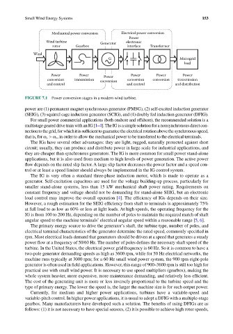
Mechanical power conversion Electrical power conversion
Power
Wind turbine Generator electronic
rotor Gearbox interface Transformer
Wind
G Microgrid
load
Power Power Power Power Power Power
conversion transmission conversion conversion conversion transmission
and control and control and distribution
FIGURE 7.1 Power conversion stages in a modern wind turbine.
power are (1) permanent magnet synchronous generator (PMSG), (2) self-excited induction generator
(SEIG), (3) squirrel cage induction generator (SCIG), and (4) doubly fed induction generator (DFIG).
For small power commercial applications (both onshore and offshore), the recommended solution is a
multistage geared drive train with an IG [1–4]. The IG is a simple solution for a nonsynchronous direct con-
nection to the grid, for which it is sufficient to guarantee the electrical rotation above the synchronous speed,
that is, for ω e > ω r , in order to allow the mechanical power to be transferred to the electrical terminals.
The IGs have several other advantages: they are light, rugged, naturally protected against short
circuit; usually, they can produce and distribute power in large scale for industrial applications, and
they are cheaper than synchronous generators. The IG is more common for small power stand-alone
applications, but it is also used from medium to high levels of power generation. The active power
flow depends on the rated slip factor. A large slip factor decreases the power factor and a speed con-
trol or at least a speed limiter should always be implemented in the IG control system.
The IG is very often a standard three-phase induction motor, which is made to operate as a
generator. Self-excitation capacitors are used for the voltage building-up process, particularly for
smaller stand-alone systems, less than 15 kW mechanical shaft power rating. Requirements on
constant frequency and voltage should not be demanding for stand-alone SEIG, but an electronic
load control may improve the overall operation [4]. The efficiency of IGs depends on their size.
However, a rough estimation for the SEIG efficiency from shaft to terminals is approximately 75%
at full load to as low as 60% or less at light loads. At high speeds, the operating frequency for the
IG is from 100 to 200 Hz, depending on the number of poles to maintain the required match of shaft
angular speed to the machine terminals’ electrical angular speed within a reasonable range [5, 6].
The primary energy source to drive the generator’s shaft, the turbine type, number of poles, and
electrical terminal characteristics of the generator determine the rated speed, commonly specified in
rpm. Most electrical loads demand that generators should be driven at a speed that generates a steady
power flow at a frequency of 50/60 Hz. The number of poles defines the necessary shaft speed of the
turbine. In the United States, the electrical power grid frequency is 60 Hz. So it is common to have a
two-pole generator demanding speeds as high as 3600 rpm, while for 50 Hz electrical networks, the
machine runs typically at 3000 rpm; for a 60 Hz small wind power system, the 900 rpm eight-pole
generator is often used in field applications. However, this range of 900–3600 rpm is still too high for
practical use with small wind power. It is necessary to use speed multipliers (gearbox), making the
whole system heavier, more expensive, more maintenance demanding, and relatively less efficient.
The cost of the generating unit is more or less inversely proportional to the turbine speed and the
type of primary energy. The lower the speed is, the larger the machine size is for such output power.
Currently, for medium and higher power applications, turbines have a variable-speed and
variable-pitch control. In higher power applications, it is usual to adopt a DFIG with a multiple-stage
gearbox. Many manufacturers have developed such a solution. The benefits of using DFIGs are as
follows: (1) it is not necessary to have special sensors, (2) it is possible to achieve high rotor speeds,