
Page 170 - Renewable Energy Devices and System with Simulations in MATLAB and ANSYS
P. 170
Small Wind Energy Systems 157
7.3 TURBINE SELECTION FOR WIND ENERGY
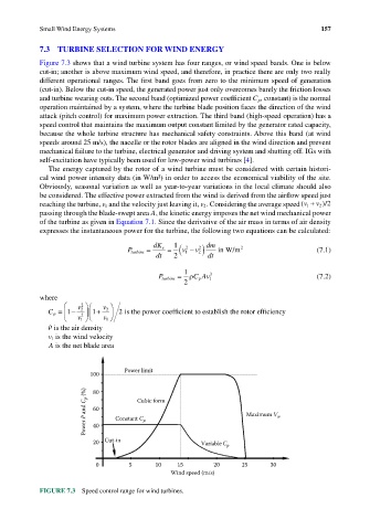
Figure 7.3 shows that a wind turbine system has four ranges, or wind speed bands. One is below
cut-in; another is above maximum wind speed, and therefore, in practice there are only two really
different operational ranges. The first band goes from zero to the minimum speed of generation
(cut-in). Below the cut-in speed, the generated power just only overcomes barely the friction losses
and turbine wearing outs. The second band (optimized power coefficient C p , constant) is the normal
operation maintained by a system, where the turbine blade position faces the direction of the wind
attack (pitch control) for maximum power extraction. The third band (high-speed operation) has a
speed control that maintains the maximum output constant limited by the generator rated capacity,
because the whole turbine structure has mechanical safety constraints. Above this band (at wind
speeds around 25 m/s), the nacelle or the rotor blades are aligned in the wind direction and prevent
mechanical failure to the turbine, electrical generator and driving system and shutting off. IGs with
self-excitation have typically been used for low-power wind turbines [4].
The energy captured by the rotor of a wind turbine must be considered with certain histori-
cal wind power intensity data (in W/m²) in order to access the economical viability of the site.
Obviously, seasonal variation as well as year-to-year variations in the local climate should also
be considered. The effective power extracted from the wind is derived from the airflow speed just
reaching the turbine, v 1 and the velocity just leaving it, v 2 . Considering the average speed (v 1 + v 2 )/2
passing through the blade-swept area A, the kinetic energy imposes the net wind mechanical power
of the turbine as given in Equation 7.1. Since the derivative of the air mass in terms of air density
expresses the instantaneous power for the turbine, the following two equations can be calculated:
v − )
1 dm
P turbine = dK e = ( 1 2 v 2 2 in W/m 2 (7.1)
dt 2 dt
1
P turbine = ρ C Av 1 3 (7.2)
p
2
where
v v
2
C p = 1 − 2 2 1 + 2 2 is the power coefficient to establish the rotor efficiency
v 1 v
1
ρ is the air density
v 1 is the wind velocity
A is the net blade area
Power limit
100
Power P and C p (%) 60 Constant C p Maximum V w
80
Cubic form
40
20 Cut-in Variable C p
0 5 10 15 20 25 30
Wind speed (m/s)
FIGURE 7.3 Speed control range for wind turbines.