
Page 167 - Renewable Energy Devices and System with Simulations in MATLAB and ANSYS
P. 167
154 Renewable Energy Devices and Systems with Simulations in MATLAB and ANSYS ®
®
Gearbox
0.040
Power losses (p.u.) 0.020 Converter
Generator
5 10 15
Wind speed (m/s)
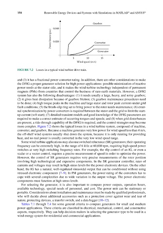
FIGURE 7.2 Losses in a typical wind turbine drive train.
and (3) it has a fractional power converter rating. In addition, there are other considerations to make
the DFIG a proper generator solution for high power applications: possible minimization of reactive
power needs at the stator side, and it makes the wind turbine technology independent of permanent
magnets (PMs) from countries that control the business of rare-earth materials. However, a DFIG
system has also the following disadvantages: (1) it needs usually a large, heavy, and noisy gearbox;
(2) it gives heat dissipation because of gearbox friction; (3) gearbox maintenance procedures need
to be done; (4) high torque peaks in the machine and large stator and rotor peak currents under grid
fault conditions; (5) the brush–slip ring set to bring power to the rotor needs maintenance; (6) exter-
nal synchronization by power converters is required between the stator and the grid to limit the start-
up current (soft start); (7) detailed transient models and good knowledge of the DFIG parameters are
required to make a correct estimate of occurring torques and speeds; and (8) when grid disturbances
are present, a ride-through capability of the DFIG is required, and the control strategies may become
more complex. Figure 7.2 shows the typical losses in a wind turbine system, composed of machine,
converter, and gearbox. Because a machine generates very low power for wind speed less than 4 m/s,
the off-shelf wind systems usually shut down the system, because it is only running for providing
heat, and no real power is usually converted in the very low wind speed range.
Some wind turbine applications may also use switched reluctance (SR) generators; their operating
frequency can be extremely high, in the range of 6 kHz at 60,000 rpm, requiring high-speed power
switches at very high switching frequency rates. For example, the slip control of an IG, or even a
scalar or a vector control, requires a precise measurement of speed in order to optimize the power.
However, the control of SR generators requires very precise measurements of the rotor position
involving high technological and expensive components. In the SR generator controller, rates of
currents and voltages may result in high stress levels for the power electronic devices. On the other
hand, the IG has a natural, well-regulated sinusoidal output that can be conditioned without using
stressed electronic components [7–9]. In PM generators, the power rating of the converters has to
cope with several complexities due to wide variation in the output voltage. The power electronic
components must function at high stress levels.
For selecting the generator, it is also important to compare power outputs, operation hours,
available technology, special needs of personnel, and cost. The power unit can be stationary or
portable. Considerations about installation and maintenance must be made by qualified professionals,
who will decide about additional accessories such as a protection cover against wear and tear of
nature, protecting devices, a transfer switch, and a data logger [10–12].
Tables 7.1 through 7.4 list some general criteria to compare generators for small and medium
power applications. These criteria are classified in electrical, mechanical, control, and constructive
aspects, respectively. They can help decision-makers in selecting the generator type to be used in a
wind energy system for residential and commercial applications.