
Page 174 - Renewable Energy Devices and System with Simulations in MATLAB and ANSYS
P. 174
Small Wind Energy Systems 161
V s Voltage with saturation
V t plotted on V × I curve X s I m I c
E g 1
Graphical solution, V X = ωC
c
operating point s
Load line curve for
–1
tan (X ) capacitor
c
l =l l m
(a) g c (b)
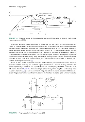
FIGURE 7.6 Scheme to obtain: (a) the magnetization curve and (b) the capacitor value for a self-excited
induction generator (SEIG).
Electronic power converters when used as a load for IGs may cause harmonic distortion and
losses. A variable power factor and some special control techniques should be adopted when using
electronic power converters. The IEEE Std. 519 establishes the limits of 2% of harmonic content for
single- and three-phase induction motors (except the category N, i.e., conventional) and 3% for high
efficiency (H and D). Active filters provide signal injection to minimize such harmonics. The cost
of passive filters can be relatively small, and the designed speed control of power plants is possible
by electronic variation of frequency, using, for example, a droop control method. The self-excitation
capacitor in stand-alone wind turbine systems, with electric or electronic control of the load, con-
tributes favorably in these cases [4].
When an RLC load is connected across the SEIG terminals, the combination of the inductive
reactance with the necessary self-excitation capacitance results in a new self-exciting reactance and
a new output voltage condition. The equivalent circuit in per unit (p.u.) of an SEIG connected to an
RL load is shown in Figure 7.7. This circuit represents a more generic per phase of the steady-state
induction machine [2, 3]. It also shows that the frequency effects on the reactance should be consid-
ered if the generator is used at different frequencies from its base frequency f b (in hertz) at which the
I L I 1 I 2 j(X 1 +X 2 )
2
R I C (R 1 +R )/F
F
I m jX m R 2 1–s
–jX Fs
jX c
F 2
I L I 1 I 2 jX 1 jX 2
R /F
R 1 R /F
2
F I C –jX c 1–s
F 2 I m jX m R 2 Fs
jX
FIGURE 7.7 Per-phase equivalent circuit of a loaded IG.