
Page 192 - Renewable Energy Devices and System with Simulations in MATLAB and ANSYS
P. 192
Power Electronics and Controls for Large Wind Turbines and Wind Farms 179
Wind turbine system
Wind power Rotor Gearbox Generator Converter Transformer Power grid
G
Input Output
Mechanical power conversion Electrical power conversion
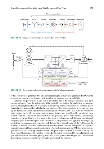
FIGURE 8.1 Energy conversion stage in a wind turbine system (WTS).
Rotor
DFIG Filter
Gearbox AC DC
DC AC Grid
IG/PMSG Chopper Transformer
V DC Pulse width modulation X filter
Grid
I Gen. Current/voltage synchronization I grid
control
Basic control loops V grid
Q
Ω gen. Power maximization Fault ride through P meas., meas.
and limitation and grid support
θ WT specic controls
Inertia Energy Power Command from
emulation storage quality DSO/TSO
Extra control features
FIGURE 8.2 Generic power electronics converter control of wind power generators.
with a synchronous generator (SG) or a permanent magnet synchronous generator (PMSG) or the
partial-scale converter-based system with a doubly fed induction generator (DFIG).
Generally, the power flow in and out of the system has to be managed carefully. The input
mechanical power from the turbines should be limited by controlling the mechanical components
such as pitch angle of rotors (θ) or direction of the yawing system. Meanwhile, the electrical power
injected to the power grid should also be regulated according to the standards or commands given
by the distribution system operator/transmission system operator (DSO/TSO). After the power flow
in the system can be fully managed, more advanced features may be achieved by introducing extra
control functions, such as the maximization of the generated power from turbines, ride-through
operation of the grid faults, and supporting functions in both normal and abnormal operations of
the power grid. In variable speed WTs, the current in the generator will typically be changed by
controlling the generator-side converter, and thereby the rotational speed of the turbines can be
adjusted to achieve maximum power production based on the available wind power. In respect to
operation under grid fault, a coordinated control of several subsystems in the WT like the generator-/
grid-side converters, braking chopper/crowbar, and pitch angle controller is necessary. Finally, the
basic control functions of the electrical system like the current regulation, DC bus stabilization, and
grid synchronization have to be quickly performed, where proportional–integral (PI) controllers or
proportional-resonant controllers are typically used to track the reference.