
Page 194 - Renewable Energy Devices and System with Simulations in MATLAB and ANSYS
P. 194
Power Electronics and Controls for Large Wind Turbines and Wind Farms 181
In order to achieve a better controllability and previously mentioned functions of the WTS, the
power electronics control are becoming an essential part and it covers more and more power rating
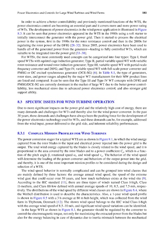
of WTs. The development of power electronics in the wind power application is illustrated in Figure
8.3. It can be seen that power electronics appeared in the WTS in the 1980s using a soft starter to
initially interconnect the generator with the power grid. Then it started to process the electrical
power in the system, first in the 1990s for the rotor resistance control and then in the 2000s for
regulating the rotor power of the DFIG [28–32]. Since 2005, power electronics have been used to
handle all of the generated power from the generator—leading to fully controlled WTs, which are
suitable to be integrated into the power grid [33–38].
For WTSs, the most commonly used concepts can be categorized into four types: Type I, fixed
speed WTSs with squirrel cage induction generator; Type II, partial variable speed WT with variable
rotor resistance and wound rotor induction generator; Type III, variable speed WT with partial-scale
frequency converter and DIFG; and Type IV, variable speed WT with full-scale power converter and
PMSG or DC excited synchronous generator (DCE-SG) [6]. In Table 8.1, the type of generators,
rotor sizes, and power ranges adopted by the major WT manufacturers for their MW product lines
are listed and compared. It can be seen that the Type III and Type IV WT concepts with DFIG and
PMSG/DCE-SG are currently dominant in the market of large WT due to the better power control-
lability, less mechanical stress due to advanced power electronics control, and also stronger grid
support ability.
8.3 SPECIFIC ISSUES FOR WIND TURBINE OPERATION
Due to more significant impacts on the power grid and the relatively high cost of energy, there are
many demands and challenges for WTs and thereby also for the wind power converter. In the past
30 years, these demands and challenges have always been the pushing force for the development of
the power electronics technology used for WTs, and these demands can be, for example, addressed
from the wind input, power delivered to the grid side, and inherent reliability performances.
8.3.1 Complex Mission Profiles for Wind Turbines
The power conversion stages for a typical WTS are as shown in Figure 8.1, in which the wind energy
captured from the rotor blades is the input and electrical power injected into the power grid is the
output. The total wind energy captured by the blades is closely related to the wind speed, and it is
proportional to the area covered by the rotor blades and to a power coefficient C , which is a func-
p
tion of the pitch angle β, rotational speed ω , and wind speed v . The behavior of the wind speed
w
r
will determine the loading of the power converter and behaviors of the output power into the grid,
and thereby, it is one of the most important mission profiles to be considered during the design and
selection of a WTS.
The wind speed behavior is normally complicated and can be grouped into wind classes that
are mainly defined by three factors: the average annual wind speed, the speed of the extreme
wind gust that could occur over 50 years, and how much turbulence exists at the wind site [9].
According to the IEC standard [11], there are three types of winds named Class I-high, Class
II-medium, and Class III-low defined with annual average speeds of 10, 8.5, and 7.5 m/s, respec-
tively. The distributions of the wind speed by different wind classes are shown in Figure 8.4, where
the Weibull distribution is used to describe the characteristics. Also, a 1-year wind speed profile
is shown in Figure 8.5 with a 3 h average at 80 m hub height, which was collected from the wind
farm in Thyborøn, Denmark [12]. The shown wind speed belongs to the IEC wind Class I-high
with the average wind speed of 8.5–10 m/s, and significant wind speed variations can be identified.
In the large WTS as shown in Figure 8.1, the generator should be regulated by the converter to
control the electromagnetic torque, not only for maximizing the extracted power from the blades but
also for the energy balancing in case of dynamics due to inertia mismatch between the mechanical