
Page 198 - Renewable Energy Devices and System with Simulations in MATLAB and ANSYS
P. 198
Power Electronics and Controls for Large Wind Turbines and Wind Farms 185
T j
120 T c
110
100
90
Temperature (°C) 70
80
60
50
40
30
20
10
0
0 1000 2000 3000 4000 5000 6000 7000 8000
Time (h)
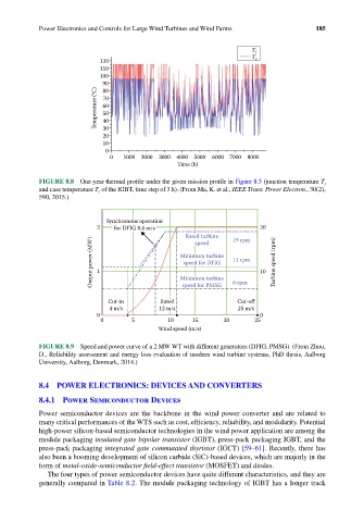
FIGURE 8.8 One-year thermal profile under the given mission profile in Figure 8.5 (junction temperature T j
and case temperature T c of the IGBT, time step of 3 h). (From Ma, K. et al., IEEE Trans. Power Electron., 30(2),
590, 2015.)
Synchronous operation
2 for DFIG 8.4 m/s 20
Rated turbine 19 rpm
Output power (MW) 1 Minimum turbine 11 rpm 10 Turbine speed (rpm)
speed
speed for DFIG
Minimum turbine
6 rpm
Cut-in Rated speed for PMSG Cut-off
4 m/s 12 m/s 25 m/s
0 0
0 5 10 15 20 25
Wind speed (m/s)
FIGURE 8.9 Speed and power curve of a 2 MW WT with different generators (DFIG, PMSG). (From Zhou,
D., Reliability assessment and energy loss evaluation of modern wind turbine systems, PhD thesis, Aalborg
University, Aalborg, Denmark, 2014.)
8.4 POWER ELECTRONICS: DEVICES AND CONVERTERS
8.4.1 Power Semiconductor Devices
Power semiconductor devices are the backbone in the wind power converter and are related to
many critical performances of the WTS such as cost, efficiency, reliability, and modularity. Potential
high-power silicon-based semiconductor technologies in the wind power application are among the
module packaging insulated gate bipolar transistor (IGBT), press-pack packaging IGBT, and the
press-pack packaging integrated gate commutated thyristor (IGCT) [59–61]. Recently, there has
also been a booming development of silicon carbide (SiC)-based devices, which are majorly in the
form of metal-oxide-semiconductor field-effect transistor (MOSFET) and diodes.
The four types of power semiconductor devices have quite different characteristics, and they are
generally compared in Table 8.2. The module packaging technology of IGBT has a longer track