
Page 203 - Renewable Energy Devices and System with Simulations in MATLAB and ANSYS
P. 203
190 Renewable Energy Devices and Systems with Simulations in MATLAB and ANSYS ®
®
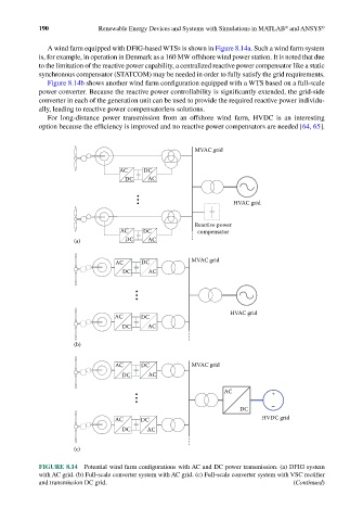
A wind farm equipped with DFIG-based WTSs is shown in Figure 8.14a. Such a wind farm system
is, for example, in operation in Denmark as a 160 MW offshore wind power station. It is noted that due
to the limitation of the reactive power capability, a centralized reactive power compensator like a static
synchronous compensator (STATCOM) may be needed in order to fully satisfy the grid requirements.
Figure 8.14b shows another wind farm configuration equipped with a WTS based on a full-scale
power converter. Because the reactive power controllability is significantly extended, the grid-side
converter in each of the generation unit can be used to provide the required reactive power individu-
ally, leading to reactive power compensatorless solutions.
For long-distance power transmission from an offshore wind farm, HVDC is an interesting
option because the efficiency is improved and no reactive power compensators are needed [64, 65].
MVAC grid
AC DC
DC AC
HVAC grid
Reactive power
AC DC compensator
(a) DC AC
AC DC MVAC grid
DC AC
HVAC grid
AC DC
DC AC
(b)
AC DC MVAC grid
DC AC
AC +
DC –
AC DC HVDC grid
DC AC
(c)
FIGURE 8.14 Potential wind farm configurations with AC and DC power transmission. (a) DFIG system
with AC grid. (b) Full-scale converter system with AC grid. (c) Full-scale converter system with VSC rectifier
and transmission DC grid. (Continued)