
Page 201 - Renewable Energy Devices and System with Simulations in MATLAB and ANSYS
P. 201
188 Renewable Energy Devices and Systems with Simulations in MATLAB and ANSYS ®
®
2L-BTB
AC AC
DC DC
G
2L-BTB
AC AC
Generator Grid
DC DC
FIGURE 8.12 Topology with paralleled voltage source converters using a winding generator with regular
windings.
8.4.3 Multilevel Converter Topologies
With the abilities of higher voltage amplitude and larger power capability, multilevel converter
topologies are becoming promising candidates for large WTs [42–44]. In order to achieve a cost-
effective solution, multilevel converters at present are normally used in 3 MW and upto 8 MW WTs
with the full-scale power converter.
The three-level neutral point diode clamped (3L-NPC) topology is one of the most commercial-
ized multilevel topologies on the market [45–47]. It is usually configured as a back-to-back (BTB)
structure in WTs, as shown in Figure 8.13.
Because the 3L-NPC BTB achieves one more output voltage level compared to the 2L-BTB
solution, the output filter size can be smaller. More importantly, the 3L-NPC BTB can double the
output voltage with the same switching devices compared to 2L-BTB—which means an extended
power capability can be obtained. However, it is found that the loss distribution is unequal between
the outer and inner switching devices in a switching arm, and this problem might lead to derated
power capacity when it is practically designed. In order to further extend the power handling ability,
it is also possible to configure several 3L-NPC BTB converters in parallel, which is similar as the
case shown in Figure 8.12.
The three-level H-bridge back-to-back (3L-HB BTB) converter is another interesting solution,
which is composed of two three-phase H-bridge converters configured in a BTB structure. It achieves
a similar output performance like the 3L-NPC BTB solution, but the unequal loss distribution and
clamped diodes can be avoided. Thereby, a more efficient and equal loading of power switching
devices and higher designed power capacity might be obtained [48–52]. A similar topology can also
be configured to have five-voltage-level output per phase, with the same half bridge of 3L-NPC BTB
[51]. However, either the 3L-HB BTB or the 5L-HB BTB solutions need an open-winding configu-
ration both for the generator and for the transformer in order to achieve isolation among each phase.
This feature has both advantages and disadvantages: On one hand, a potential fault-tolerant ability is
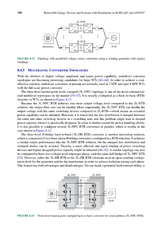
3L-NPC 3L-NPC
G
Generator Grid
FIGURE 8.13 Three-level neutral point clamped back-to-back converter for wind turbines (3L-NPC BTB).