
Page 197 - Renewable Energy Devices and System with Simulations in MATLAB and ANSYS
P. 197
184 Renewable Energy Devices and Systems with Simulations in MATLAB and ANSYS ®
®
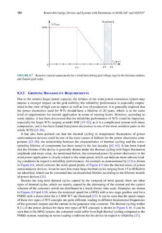
Dead band
I /I rated
q
100%
V (p.u.)
g
0
0.5 0.9 1.0
FIGURE 8.7 Reactive current requirements for a wind farm during grid voltage sags by the German-onshore
and Danish grid codes.
8.3.3 Growing Reliability Requirements
Due to the relative larger power capacity, the failures of the wind power conversion system may
impose a stronger impact on the grid stability; the reliability performance is especially empha-
sized in the view of high cost to repair as well as loss of production. It is generally required that
the power electronics used for WTs should have a lifetime of 20 years, which is at the same
level of requirements for aircraft application in terms of running hours. However, according to
some studies, it has been discovered that the reliability performance of WTs could be improved,
especially for larger WTs ranging at multi-MW [19–22], as it is a complicated system with many
components, and it has been found that power electronics is one of the most sensitive parts in the
whole WTS [23–26].
It has also been pointed out that the thermal cycling or temperature fluctuations of power
semiconductor devices could be one of the main causes of failures for the power electronics com-
ponents [23–26]; the relationship between the characteristics of thermal cycling and the corre-
sponding lifetime of components has been tested in the last decades [62, 63]. It has been found
that the lifetime of the device is generally shorter under the thermal cycling with larger fluctuation
amplitude and mean value. As mentioned before, the converted power by power electronics in the
wind power application is closely related to the wind speed, which can indicate more adverse load-
ing conditions in respect to reliability performances. An example as demonstrated by [12] is shown
in Figure 8.8, which converts the wind speed profile of Figure 8.5 into the thermal stress of power
semiconductor devices. It can be seen that many large thermal cycles ranging from 15 to 90 Kelvin
are identified, which can be converted into an unsatisfied lifetime according to the lifetime models
of power devices [23].
Besides the long-term thermal cycles caused by the variation of wind speeds, there are other
types of thermal cycles, which are mainly caused by the alternating of the current and the control
schemes of the converter, which are distributed in a much shorter time scale. Examples are shown
in Figures 8.9 and 8.10, where the rotational speed for a DFIG with a two stage gearbox and for a
PMSG with a direct drive for a 2 MW WT are illustrated [27]. It can be seen that the speed ranges
of these two types of WT concepts are quite different, leading to different fundamental frequencies
of the generator outputs and the current in the generator-side converter. The thermal cycling within
0.2 s of the power devices for these two types of WT concepts is shown in Figure 8.10. It can be
seen that in the DFIG system, the converter could suffer from high thermal cycling compared to the
PMSG system, resulting in worse loading conditions for the device in respect to reliability [27].