
Page 200 - Renewable Energy Devices and System with Simulations in MATLAB and ANSYS
P. 200
Power Electronics and Controls for Large Wind Turbines and Wind Farms 187
connection), and better cooling capability. However, IGCTs have not yet been mass adopted in the
WTS due to the relatively high cost. As the power capacity of WTs grows even up to 10 MW, it can
be expected that the press-pack packaging technology may become more promising for the future
WTS, where medium-voltage level could become a need.
Besides silicon power devices, SiC-based devices, which are claimed to have better switching
characteristics and lower power losses, are a promising technology in future wind power systems.
Although the existing power capacity of SiC devices is still not high enough for the wind power
conversion, these new devices have shown great potential for some future wind converter structures,
which consist of paralleled/cascaded converter units.
It is expected that the WT concepts Type III and Type IV will continue to be the dominant sys-
tems in the next decades. However, in respect to the converter topologies, there are more flexibilities,
which will be discussed in the following.
8.4.2 Two-Level Converter Topologies
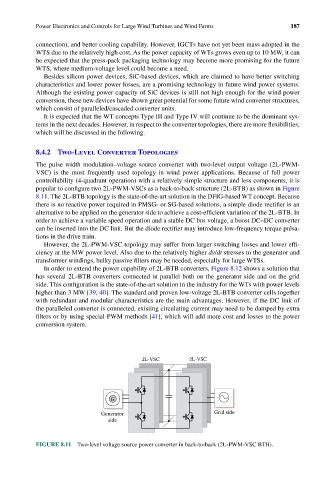
The pulse width modulation–voltage source converter with two-level output voltage (2L-PWM-
VSC) is the most frequently used topology in wind power applications. Because of full power
controllability (4-quadrant operation) with a relatively simple structure and less components, it is
popular to configure two 2L-PWM-VSCs as a back-to-back structure (2L-BTB) as shown in Figure
8.11. The 2L-BTB topology is the state-of-the-art solution in the DFIG-based WT concept. Because
there is no reactive power required in PMSG- or SG-based solutions, a simple diode rectifier is an
alternative to be applied on the generator side to achieve a cost-efficient variation of the 2L-BTB. In
order to achieve a variable speed operation and a stable DC bus voltage, a boost DC–DC converter
can be inserted into the DC link. But the diode rectifier may introduce low-frequency torque pulsa-
tions in the drive train.
However, the 2L-PWM-VSC topology may suffer from larger switching losses and lower effi-
ciency at the MW power level. Also due to the relatively higher dv/dt stresses to the generator and
transformer windings, bulky passive filters may be needed, especially for large WTSs.
In order to extend the power capability of 2L-BTB converters, Figure 8.12 shows a solution that
has several 2L-BTB converters connected in parallel both on the generator side and on the grid
side. This configuration is the state-of-the-art solution in the industry for the WTs with power levels
higher than 3 MW [39, 40]. The standard and proven low-voltage 2L-BTB converter cells together
with redundant and modular characteristics are the main advantages. However, if the DC link of
the paralleled converter is connected, existing circulating current may need to be damped by extra
filters or by using special PWM methods [41], which will add more cost and losses to the power
conversion system.
2L-VSC 2L-VSC
G
Generator Grid side
side
FIGURE 8.11 Two-level voltage source power converter in back-to-back (2L-PWM-VSC BTB).