
Page 204 - Renewable Energy Devices and System with Simulations in MATLAB and ANSYS
P. 204
Power Electronics and Controls for Large Wind Turbines and Wind Farms 191
AC MVDC grid
DC
DC AC +
AC DC –
HVDC grid
Solid-state transformer
AC
(DC/DC transformer)
DC
(d)
AC DC MVAC grid
DC AC
+
–
HVDC grid
AC DC
DC AC
(e)
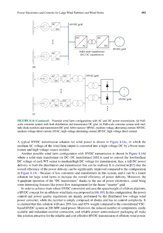
FIGURE 8.14 (Continued) Potential wind farm configurations with AC and DC power transmission. (d) Full-
scale converter system with both distribution and transmission DC grid. (e) Full-scale converter system with mul-
tiple diode rectifiers and transmission DC grid. Abbreviations: MVAC, medium-voltage alternating current; MVDC,
medium-voltage direct current; HVAC, high-voltage alternating current; HVDC, high-voltage direct current.
A typical HVDC transmission solution for wind power is shown in Figure 8.14c, in which the
medium AC voltage of the wind farm output is converted into a high-voltage DC by a boost trans-
former and high-voltage source rectifier.
Another possible wind farm configuration with HVDC transmission is shown in Figure 8.14d
where a solid-state transformer (or DC–DC transformer) [66] is used to convert the low/medium
DC voltage of each WT output to medium/high DC voltage for transmission; thus, a full DC power
delivery in both the distribution and transmission line can be realized. It is claimed in [67] that the
overall efficiency of the power delivery can be significantly improved compared to the configuration
in Figure 8.14c—because of less converters and transformers in this system, and it can be a future
solution for large wind farms to increase the overall efficiency of power delivery. Moreover, the
4-quadrant operation of the “DC transformer,” thanks to the use of power electronics, could bring
some interesting features like power flow management for the future “smarter” grid.
In order to achieve more robust HVDC conversion and save the space/weight of offshore platform,
a HVDC concept for an offshore wind farm was proposed in [68, 69]. In this configuration, the power
control and power quality regulations are mainly performed by the distributed low-voltage wind
power converter, while the rectifier is simply composed of diodes and has no control complexity. It
is claimed that this solution will save 20% loss and 65% weight compared to the conventional VSC-
based HVDC system at 200 MW rated power. Moreover, the reduced number of components, easily
scalable and redundant rectifier connection, and reliable power semiconductor packaging all make
this solution attractive for the reliable and cost-effective HVDC transmission of offshore wind power.