
Page 209 - Renewable Energy Devices and System with Simulations in MATLAB and ANSYS
P. 209
196 Renewable Energy Devices and Systems with Simulations in MATLAB and ANSYS ®
®
Similarly, Equations 8.9 through 8.12 describe the dynamic model of the PMSG:
0 − 1 dλ dq
dq
dq
dq
u s = R ss + pω m λ s + s (8.9)
i
1 0 dt
ss +
d
λ s = Li d ψ r (8.10)
q
λ s = Li q (8.11)
ss
Te =ψ q (8.12)
p i rs
where
u represents voltage
R represents resistance
i is the current
λ represents flux linkage
L and M are inductances
p is the pole pairs
Te is the electrical torque produced
ψ is the flux linkage due to the permanent magnet
r
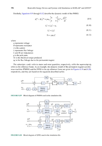
The subscripts s and r refer to stator and rotor quantities, respectively, while the superscript dq
refers to the reference frame. As an example, the dynamic model of the permanent magnet synchro-
nous machine (PMSM) and the DFIG in the dq reference frame are given in Figures 8.19 and 8.20,
respectively, and they are based on the equations described earlier.
Rs φ pm
U s dq + – λ s dq – I s dq p
∫ 1/L s T e
–
ω m
p Matrix
gain-K
FIGURE 8.19 Block diagram of PMSM used in the simulation file.
Rs
U dq + – λ dq + I s dq
s
∫ s Lr Gain
– +
ω s T
Matrix –Msr Outer e
gain-K product
λ dq
r
Rr
U r dq + – λ r dq + I r dq
– ∫ Ls + Gain
ω –pω m Matrix
s
gain-K –Msr
λ dq
s
FIGURE 8.20 Block diagram of DFIG used in the simulation file.