
Page 210 - Renewable Energy Devices and System with Simulations in MATLAB and ANSYS
P. 210
Power Electronics and Controls for Large Wind Turbines and Wind Farms 197
8.6.3 Electrical Model of Converter and Control
The converter and electrical control models are divided into the generator side and the grid side. An
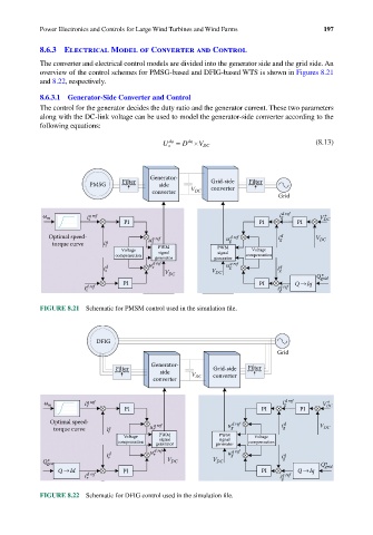
overview of the control schemes for PMSG-based and DFIG-based WTS is shown in Figures 8.21
and 8.22, respectively.
8.6.3.1 Generator-Side Converter and Control
The control for the generator decides the duty ratio and the generator current. These two parameters
along with the DC-link voltage can be used to model the generator-side converter according to the
following equations:
dq
dq
U s = D ×V DC (8.13)
Generator-
PMSG Filter side Grid-side Filter
converter
converter V DC
Grid
ω m i s q ref i g d ref V *
DC
PI PI PI
Optimal speed- u q ref u d ref i g d V DC
torque curve i s q s PWM g
Voltage PWM Voltage
signal
signal
compensation generator generator compensation
s
g
i d s u d ref V V DC u q ref i g q
DC
*
Q grid
PI PI Q Iq
i d ref i g q ref
s
FIGURE 8.21 Schematic for PMSM control used in the simulation file.
DFIG
Grid
Generator-
Filter Grid-side Filter
side V
converter DC converter
*
g
ω m i q ref i d ref V DC
r
PI PI PI
Optimal speed- q ref d ref d
torque curve i r q u r u g i g V DC
Voltage PWM PWM Voltage
signal
signal
compensation generator generator compensation
i r d u r d ref u g q ref i g q
*
Q gen V DC V DC Q* grid
Q Id PI PI Q Iq
i d ref i g q ref
r
FIGURE 8.22 Schematic for DFIG control used in the simulation file.