
Page 207 - Renewable Energy Devices and System with Simulations in MATLAB and ANSYS
P. 207
194 Renewable Energy Devices and Systems with Simulations in MATLAB and ANSYS ®
®
further step ahead, the thermal models of power semiconductor are also included, which enable a
deeper study on the reliability-related performance of the power electronics system.
The section starts with an overview of the complete WTS models in Section 8.6.1. Section
8.6.2 describes the model for the mechanical parts where the input is a wind speed profile and the
output is the shaft torque and speed of the blades, and the generator models are also described.
In the attached simulation files, two generator technologies for wind power application have been
considered—the PMSG and the DFIG. Section 8.6.3 describes the electrical parts with the con-
verter models and the control techniques used. To keep the descriptions simple, the thermal parts
of the power semiconductors in the simulation file are not given in this chapter, but they are cited
in several reference papers, which involve loss modeling and thermal impedance modeling of the
power semiconductor devices.
8.6.1 Overview of the Models and Relationship
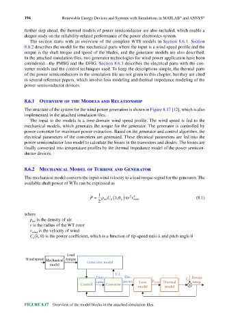
The structure of the system for the wind power generation is shown in Figure 8.17 [12], which is also
implemented in the attached simulation files.
The input to the models is a time-domain wind speed profile. The wind speed is fed to the
mechanical models, which generates the torque for the generator. The generator is controlled by
power converter for maximum power extraction. Based on the generator and control algorithm, the
electrical parameters of the converters are generated. These electrical parameters are fed into the
power semiconductor loss model to calculate the losses in the transistors and diodes. The losses are
finally converted into temperature profiles by the thermal impedance model of the power semicon-
ductor devices.
8.6.2 Mechanical Model of Turbine and Generator
The mechanical model converts the input wind velocity to a load torque signal for the generator. The
available shaft power of WTs can be expressed as
1
p)
P = ρ air C p(λ θπ rv wind (8.1)
23
,
2
where
ρ is the density of air
air
r is the radius of the WT rotor
v wind is the velocity of wind
C (λ, θ) is the power coefficient, which is a function of tip-speed ratio λ and pitch angle θ
p
Load
Wind speed Mechanical torque
model Generator model
V, I
Duty Elec. T a Device
ratio param Loss P LOSS Thermal temp.
Control Converter
model model
FIGURE 8.17 Overview of the model blocks in the attached simulation files.