
Page 206 - Renewable Energy Devices and System with Simulations in MATLAB and ANSYS
P. 206
Power Electronics and Controls for Large Wind Turbines and Wind Farms 193
MVAC grid
HVAC
AC DC grid
DC AC
AC
DC
AC DC Reactive power
DC AC compensator
(a)
MVAC grid
AC DC
DC AC
HVAC
DC grid
AC
Reactive power
AC DC compensator
DC AC
(b)
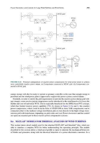
FIGURE 8.16 Potential configurations of reactive power compensation for wind power plants to achieve
more controllable reactive power output. (a) Compensator connected to MVAC grid. (b) Compensator con-
nected to HVAC grid.
energy storage will also be ready to operate as primary controller in the case that enough energy is
prestored and the wind power plant is approved to support this power system control feature.
Similarly, in order to satisfy the grid requirements to provide the reactive power during grid volt-
age changes, some reactive power compensator can be introduced in the wind farm level to lower the
burden and cost of individual WTS. This is especially beneficial for the DFIG-based WT concept,
which has limited reactive power capability [70]. As shown in Figure 8.16a and b, this reactive
power compensator, which could be in the form of STATCOM or static VAR compensator, can be
connected either to the medium-voltage distribution grid or even directly to the high-voltage trans-
mission grid with transformer, depending on grid codes and cost. Power electronics and the control
are again an essential part in these reactive power compensator systems.
®
8.6 MATLAB MODELS FOR THERMAL ANALYSIS OF WIND TURBINES
®
®
This section shows detail models used for the attached MATLAB and Simulink files, which are
able to simulate a complete WTS for better understanding the operating principle. The models
described in this section utilize a wind speed profile as input to simulate the mechanical behaviors
of blades and generator, along with the electrical behaviors of a power electronics converter. As a