
Page 223 - Renewable Energy Devices and System with Simulations in MATLAB and ANSYS
P. 223
210 Renewable Energy Devices and Systems with Simulations in MATLAB and ANSYS ®
®
9.1 INTRODUCTION
Wind energy is penetrating electric power systems at a high pace, such that in 2016 it accounted for
more than 360 GW of installed power [1–24]. The technology of wind energy harnessing has evolved
rapidly in the last 40 years with decisive progress in the wind turbine (WT) design, tower construction,
electric generator, and power electronics technology, including interfacing to local and national electric
power grids [1–4]. The power rating of WTs has increased steadily since 1980 with the main motivation
being the reduction of the energy cost [25], and large 8 MW units were first installed and commissioned
in 2014. From an economic point of view, it is interesting to note that the levelized cost of electricity for
onshore wind farms, which is expected to continue to decrease due to technological developments, is
already, in regions such as Germany, comparable with that of coal power plants [5].
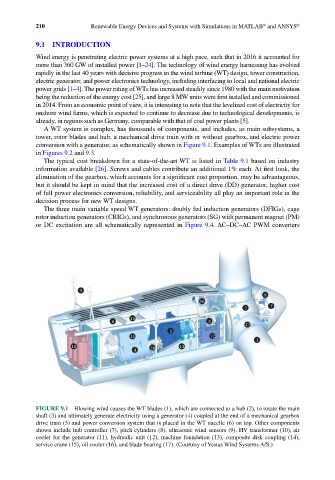
A WT system is complex, has thousands of components, and includes, as main subsystems, a
tower, rotor blades and hub, a mechanical drive train with or without gearbox, and electric power
conversion with a generator, as schematically shown in Figure 9.1. Examples of WTs are illustrated
in Figures 9.2 and 9.3.
The typical cost breakdown for a state-of-the-art WT is listed in Table 9.1 based on industry
information available [26]. Screws and cables contribute an additional 1% each. At first look, the
elimination of the gearbox, which accounts for a significant cost proportion, may be advantageous,
but it should be kept in mind that the increased cost of a direct drive (DD) generator, higher cost
of full power electronics conversion, reliability, and serviceability all play an important role in the
decision process for new WT designs.
The three main variable speed WT generators: doubly fed induction generators (DFIGs), cage
rotor induction generators (CRIGs), and synchronous generators (SG) with permanent magnet (PM)
or DC excitation are all schematically represented in Figure 9.4. AC–DC–AC PWM converters
9
8
16
2 7
15
6 3
17
5
11 12
1
10 14 13
4
FIGURE 9.1 Blowing wind causes the WT blades (1), which are connected to a hub (2), to rotate the main
shaft (3) and ultimately generate electricity using a generator (4) coupled at the end of a mechanical gearbox
drive train (5) and power conversion system that is placed in the WT nacelle (6) on top. Other components
shown include hub controller (7), pitch cylinders (8), ultrasonic wind sensors (9), HV transformer (10), air
cooler for the generator (11), hydraulic unit (12), machine foundation (13), composite disk coupling (14),
service crane (15), oil cooler (16), and blade bearing (17). (Courtesy of Vestas Wind Systems A/S.)