
Page 224 - Renewable Energy Devices and System with Simulations in MATLAB and ANSYS
P. 224
Electric Generators and their Control for Large Wind Turbines 211
4
3
2
1
FIGURE 9.2 Vestas multi-MW variable speed WT system including mechanical gearbox (1), generator (2),
power electronic controls (3), and cooler top (4). (Courtesy of Vestas Wind Systems A/S.)
1
2
3 4
5
6
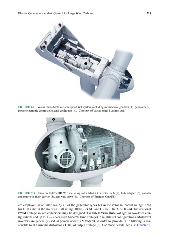
FIGURE 9.3 Enercon E-126 DD WT including rotor blades (1), rotor hub (2), hub adapter (3), annular
generator (4), main carrier (5), and yaw drive (6). (Courtesy of Enercon GmbH.)
are employed as an interface by all of the generator types but in the rotor (at partial rating: 30%)
for DFIG and in the stator (at full rating: 100%) for SG and CRIG. The AC–DC–AC bidirectional
PWM voltage source converters may be designed at 400/690 Vrms (line voltage) in two-level con-
figurations and up to 3.2–3.6 or even 6 kVrms (line voltage) in multilevel configurations. Multilevel
inverters are generally used at powers above 3 MVA/unit, in order to provide, with filtering, a rea-
sonable total harmonic distortion (THD) of output voltage [8]. For more details, see also Chapter 8.