
Page 225 - Renewable Energy Devices and System with Simulations in MATLAB and ANSYS
P. 225
212 Renewable Energy Devices and Systems with Simulations in MATLAB and ANSYS ®
®
TABLE 9.1
Main Components and Typical Cost Breakdown for State-of-the-Art Type
C Multi-MW Wind Turbines Employing a Doubly Fed Induction Generator
Component Cost % Comments
Tower 26 Manufactured from sections of rolled steel or from concrete. Typical
height is 100 m.
Rotor blades 22 Made of composite materials with carbon fiber added for mechanical
strength. Blades are typically longer than 60 m each.
Rotor hub 1 Casted from iron in a single piece.
Rotor bearings 1 Designed to withstand significant and variable radial and axial loads.
Main shaft 2 Transfers the mechanical power from the WT rotor to the gearbox.
Main frame 3 Manufactured from steel, must be designed for low weight and high
mechanical strength.
Gearbox 13 Converts the low speed and high torque from the wind side to high
speed and low torque for the generator side.
Generator 3 Apart from DFIG, other commonly used generator types include
PMSM, CRIG, and DCE-SG.
Yaw system 1 Rotates the nacelle to follow the wind direction in order to maximize
the energy harvesting.
Pitch system 3 Adjusts the angle of the blades for best wind incidence in order to
maximize the energy harvesting.
Power converter 5 Power electronics for AC–AC conversion, with or without (less
common) DC link.
Transformer 4 Placed at the generator output; it increases voltage and reduces
current and, if installed in the nacelle, results in smaller cable size
and reduced losses from the nacelle to the base of the tower.
Brake system 1 Disk type used for safety and maintenance.
Nacelle housing 1 Typically made of fiber glass in order to achieve reduced weight
and cost.
f 1
f 2 P in P o
D
Q Q
DFIG
Wind Gear f 1 AC AC Filter
S
DC DC Grid
DCE-SG/PMSG V DC PWM PWM
X
f 1 Current/Voltage Grid f
I control control synchronization I grid
V DC
Ambient I Gen. Basic control functions V grid
temperature CRIG Power maximization Fault ride through
gen. and limitation and grid support P meas. , Q meas.
θ WTs' specific functions
Power
Inertia
Mission profiles emulation Energy quality
storage
Ancillary services Supervisory command
Communication Monitoring and control from DSO/TSO
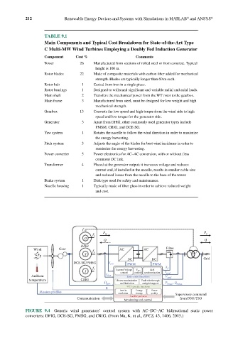
FIGURE 9.4 Generic wind generators’ control system with AC–DC–AC bidirectional static power
converters: DFIG, DCE-SG, PMSG, and CRIG. (From Ma, K. et al., EPCS, 43, 1406, 2015.)